-
Match the complete marking
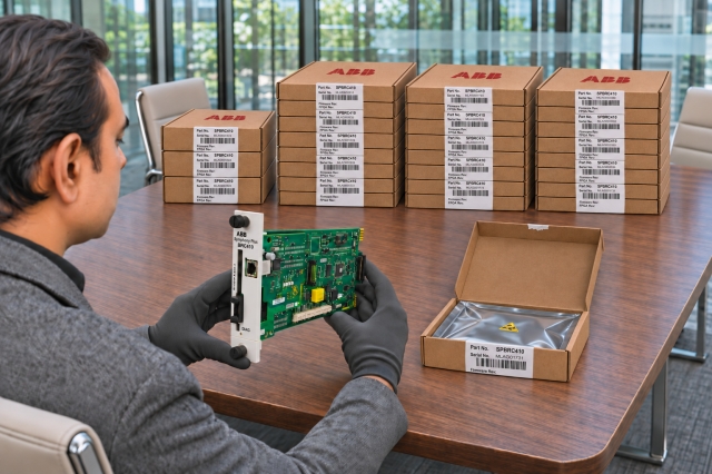
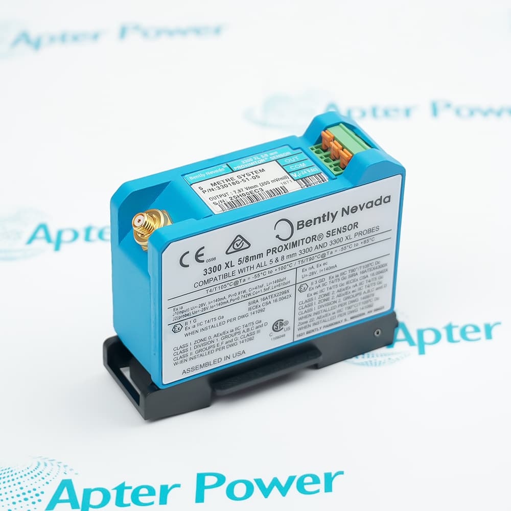
Include 330930-060-04-05 and every revision or approval marking visible on the item. Keep the exact reference on your enquiry and quotation. -
Check the offered item before ordering
Request available label and interface photos. Have your maintenance team compare the offered 330930-060-04-05 reference with the installed equipment and applicable Bently Nevada documentation.
Technical specifications for 330930-060-04-05
-
Manufacturer:Bently Nevada
-
Product Category:Machinery Monitoring Systems
-
Spare Part Number:330930-060-04-05
-
Weight:0.5 kg
-
Tariff Code:8537101190
-
Cable family:3300 XL NSv
-
Cable length:6.0 m
-
Armor material:AISI 302 stainless steel
-
Armor jacket:FEP
-
Connector protection:Protector selected at the cable joint
-
Approval selection:Multiple approvals
-
Center resistance:0.220 ohm/m
-
Shield resistance:0.066 ohm/m
-
Capacitance:69.9 pF/m typical
-
Connector material:Gold-plated brass
-
Minimum bend radius:25.4 mm
-
Maximum connector torque:0.56 N m; finger-tight recommended
-
Cable temperature:-52 to +177 deg C
-
Matched-system lengths:5 m or 7 m
-
Matched-system range:1.5 mm
-
Matched-system scale:7.87 V/mm (200 mV/mil)
Information
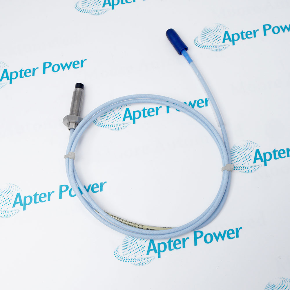
- Bently Nevada 330930-060-04-05 is a 6.0 m FEP-jacketed armored extension cable that completes a matched NSv proximity transducer chain.
Protection package: FEP armor jacket and connector protector.
Electrical construction: 69.9 pF/m typical capacitance; 0.220 ohm/m center resistance.
Stainless-steel armor and an FEP jacket protect the coaxial path. Maintain the 25.4 mm minimum bend radius, support the armor independently and keep both gold-plated ClickLoc interfaces clean, dry and finger-tight.
Published range and scale are matched-system properties. After replacement, confirm total length, restore the documented gap or bias and prove the monitor response against the machine baseline.
-
Bently Nevada 330930-060-04-05 official technical excerpt
Selected manufacturer pages covering the applicable family, technical data and exact order-code fields. -
Bently Nevada 330930-060-04-05 engineering guide
Apter Power installation, configuration, diagnostic and acceptance guidance.
Platform applications: The uses below require the documented 3300 XL NSv proximity transducer system companion components and approved machine drawing.
-
Installed signal path
Complete the coaxial signal path between an NSv probe and the matching Proximitor Sensor. -
Condition-monitoring service
Use the cable only with the documented transducer and monitor or conditioner family assigned to the machine channel. -
Maintenance replacement
Match conductor count, connector, length, armor and routing before disturbing the installed cable. -
Channel acceptance
Prove continuity, insulation condition and returned channel response against the approved machine baseline.
Match 330930-060-04-05, cable length, connector and conductor construction with the installed record.
Place the monitor channel and machine in the approved maintenance state before disconnecting or checking continuity.
Keep contacts dry and clean; do not use the connector or terminal lugs as a pulling point.
Preserve bend clearance, armor support, abrasion protection and separation from damaging heat or sharp edges.
Label each conductor and shield before removal, then compare end-to-end continuity with the applicable wiring drawing.
After reconnection, verify the expected monitor indication and operating response before return to service.
Alternative Names
Technical notes
Electrical relationship: The 6.0 m cable combines with the installed probe lead to create the Proximitor total system length.
Mechanical relationship: Maintain 25.4 mm bend radius, connector protection and independent armor support throughout the route.
Technical reference: Bently Nevada 3300 XL NSv Proximity Transducer System Datasheet, 147385 Rev. R.

FAQ View All FAQ
-
Which probe lead completes the intended chain with 330930-060-04-05?Add the installed NSv probe lead to the 6.0 m cable and require the total to equal the selected Proximitor system length before connection.
-
How should the armored route of 330930-060-04-05 be installed?Support the AISI 302 armor independently, keep bends at or above 25.4 mm radius and prevent abrasion, crushing or tensile loading at either joint.
-
What connector checks apply before mating 330930-060-04-05?Inspect gold-plated contacts for moisture, debris and damage, align them fully, connect finger-tight and do not exceed 0.56 N m.
-
How should cable resistance be used when diagnosing 330930-060-04-05?Compare isolated end-to-end center and shield resistance with the documented cable length and inspect connectors before concluding that a Proximitor has failed.
-
What temperature boundary applies to the route of 330930-060-04-05?Keep the cable and its protected joints inside the documented -52 to +177 deg C cable range while also respecting the lower limits of companion components.
-
How does changing 330930-060-04-05 affect NSv calibration?Cable length and capacitance are part of the matched electrical chain, so a different length requires a compatible Proximitor-length configuration rather than a route-only substitution.
-
What proves the channel after replacing 330930-060-04-05?Confirm total chain length, restore the documented gap or bias and compare monitor response with the accepted machine baseline.
-
What handover data is required for 330930-060-04-05?Retain the complete marking, probe and Proximitor identities, connector condition, final route, gap or bias and operating response.
Supporting new and legacy automation
-
Please try to be as accurate as possible with your search.
-
We can quote you on 1000s of specialist parts, even if they are not listed on our website.
-
We can't find any results for “”.
Related cases and sourcing guidance
View all case studiesYou May Also Like
Product Browsing History
-
Whatsapp: +86 18030235313
Send us a message. -
sales13@apterpower.com
Complete our online form. -
+86 18030235313
Speak to our team in your native language.