-
Match the complete marking
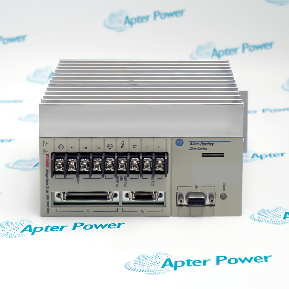
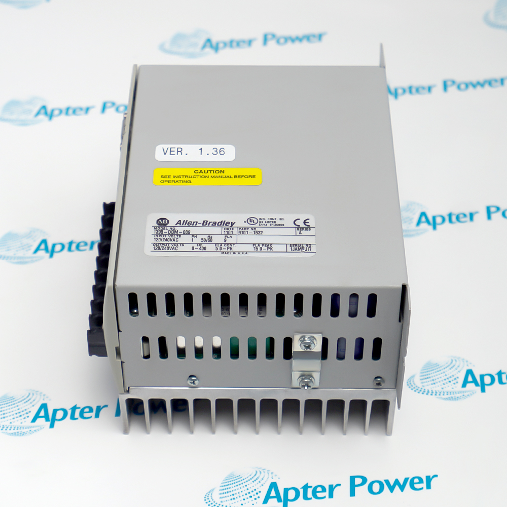
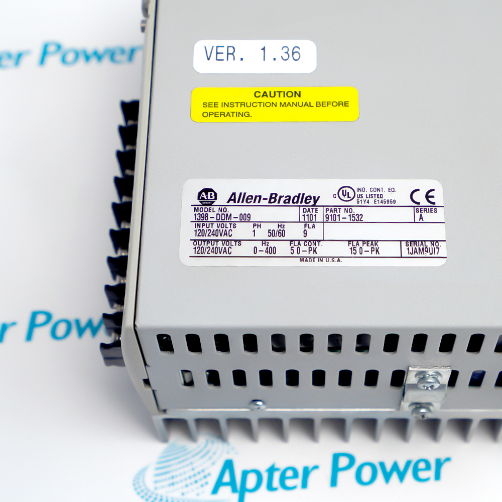
Match the full 1398-DDM-009 marking, electrical input and motor/feedback pairing with the installed axis before ordering.
-
Check the offered item before ordering
Request photos of the offered 1398-DDM-009 and have your maintenance team compare them with the installed drive and applicable Rockwell Automation ULTRA 100 documentation before ordering.
Technical specifications for 1398-DDM-009
-
Manufacturer:Allen-Bradley
-
Product Category:Servo Drives
-
Spare Part Number:1398-DDM-009
-
Weight:9.68 kg
-
Tariff Code:8537101190
-
Drive variant:Universal drive; 1398-DDM-009X is the distinct indexing variant
-
Continuous output power:1000 W
-
AC supply:100–240 V AC nominal, single phase, 47–63 Hz
-
AC input current:9 A rms
-
Peak output current:15 A
-
Continuous output current:5 A peak basis in source table
-
DC bus range:141–339 V DC
-
Digital I/O supply:External 12–24 V DC
-
Command choices:±10 V analog, presets, encoder follower, step/direction or CW/CCW
-
Serial setup:RS-232 or four-wire RS-485; 1200–19200 baud
-
Digital inputs:Four selectable active-high inputs and dedicated ENABLE
-
Digital outputs:Two selectable active-high outputs and two dedicated relay outputs
-
Current-limit input:0–10 V single-ended analog
-
Monitoring output:Selectable ±10 V analog, for monitoring only
-
Motor feedback:Motor-mounted incremental encoder and Hall inputs
-
Motor encoder output:Differential line-driver division by 1, 2, 4 or 8
Information
- The 1398-DDM-009 sits between a single-phase AC supply, an external command source and a matched brushless servo motor. Software parameters define its control loops and I/O behavior.
Command path: Analog, presets, encoder follower or step pulses
Setup path: RS-232 or four-wire RS-485 serial configuration
A microcontroller calculates current, velocity, position and motor commutation loops. An external controller can provide a ±10 V analog command, preset selection, quadrature encoder follower input, step/direction or CW/CCW pulse control. The motor-mounted encoder supplies feedback, and a selectable differential encoder output can be divided by 1, 2, 4 or 8 for the receiving controller.
Setup and diagnostics use the front-panel serial interface with RS-232 or four-wire RS-485. The drive has dedicated ENABLE and relay status functions plus selectable digital I/O. The ±10 V analog output is a monitoring signal and is not intended as a control reference; verify the selected mode, I/O power and parameter file before commissioning.
-
1398-DDM-009 Technical Reference
Rockwell Automation excerpt · PDF, 7 pages. ULTRA 100 command interfaces, 1398-DDM-009 catalog identity and electrical ratings. -
1398-DDM-009 Installation & Commissioning Guide
Apter Power field guide · PDF, 4 pages. Power and command paths, I/O setup, controlled motion tests and fault isolation.
Platform applications: Select a documented command interface and match the motor, cable, feedback and protection scheme to the installed axis; the -009X indexing feature is a separate catalog variant.
-
Analog velocity or torque axis
Use a qualified ±10 V controller output and verify command polarity, scaling and the drive's active velocity or torque mode before coupling the load. -
Pulse-controlled position axis
Use step/direction or CW/CCW command wiring with the applicable differential or TTL source limits, then test direction and pulse count with the mechanism secured. -
Encoder follower axis
Feed the documented quadrature encoder interface for electronic gearing after confirming signal levels, cable shielding and commanded direction against the master axis. -
Preset-command machine axis
Use the selectable active-high inputs for approved preset torque or velocity states; confirm external I/O supply, assignment and ENABLE behavior during each state transition.
Disconnect AC input, wait for bus discharge and verify the DC bus is safe before touching motor or power terminals; follow the manual's high-voltage warning and site procedure.
Provide the specified external 12–24 V DC source for command and status I/O; do not assume the integrated drive power supply powers those field circuits.
Check that the installed reference is 1398-DDM-009 without X or DeviceNet suffix, and reconcile the expected operating mode and connector set.
Compare the selected motor, encoder/Hall wiring, thermostat and parameter file with the machine record before enabling torque.
Size upstream protection, AC line filter and enclosure ventilation to the documented 9 A rms input and drive losses; use the site-approved design.
Start with ENABLE inhibited, verify serial setup and status, test the command direction at low risk, then record fault response and final axis behavior.
Alternative Names
Technical notes
Variant boundary: Rockwell lists 1398-DDM-009 as the universal 1000 W drive and 1398-DDM-009X as the separate indexing variant.
I/O boundary: The drive's selectable and dedicated digital I/O uses an external 12–24 V DC supply; the analog output is intended for monitoring.
Technical reference: ULTRA 100 Series Drives Installation Manual, Rockwell Automation publication 1398-5.2 / 1398-UM002.

FAQ View All FAQ
-
How do I distinguish 1398-DDM-009 from 1398-DDM-009X before replacement?Check the complete nameplate suffix and existing application program. Rockwell lists 1398-DDM-009 as the universal drive and -009X as the indexing drive; matching 1000 W power does not establish equivalent indexing capability.
-
Why might a 1398-DDM-009 show power but ignore an ENABLE command?Verify the external 12–24 V DC I/O supply, ENABLE wiring, active-high level and drive status independently of the AC line. Check the configured fault/reset assignments before applying a motion command.
-
What should I verify before connecting a ±10 V command to 1398-DDM-009?Check the controller's voltage range, command polarity, 13.3 kΩ input loading and active velocity or torque mode. With the axis secured, command a low-level signal and compare actual direction and speed or torque response.
-
Can the analog output of 1398-DDM-009 serve as a motion-control reference?No. The selectable ±10 V analog output is specified for monitoring and has ripple that makes it unsuitable as a control signal. Use an approved controller output for the command and test the monitor only as an observation channel.
-
How should I choose RS-232 or RS-485 for 1398-DDM-009 setup?Use RS-232 for a documented single-axis setup or four-wire RS-485 for the supported multi-axis arrangement. Match the wiring, baud rate and parity on the host and drive, then read back the stored parameter set.
-
What must be checked when a 1398-DDM-009 motor rotates in the wrong direction?Inhibit the load first. Compare command polarity or pulse-direction input, motor phase and encoder/Hall feedback wiring against the approved axis drawing, then perform a controlled low-speed direction test before reconnecting the process.
-
How do I confirm the current limit on 1398-DDM-009?Check whether the dedicated 0–10 V external current-limit input is wired or the peak-current value is set in software. Read back the active configuration and compare it with motor and load ratings before enabling the axis.
-
What evidence should I capture after commissioning 1398-DDM-009?Record the exact drive and motor markings, stored parameters, selected command mode, serial settings, I/O supply, ENABLE and relay states, representative motion response and any fault history under the site's acceptance procedure.
Supporting new and legacy automation
-
Please try to be as accurate as possible with your search.
-
We can quote you on 1000s of specialist parts, even if they are not listed on our website.
-
We can't find any results for “”.
Related cases and sourcing guidance
View all case studiesYou May Also Like
Product Browsing History
-
Whatsapp: +86 18030235313
Send us a message. -
sales13@apterpower.com
Complete our online form. -
+86 18030235313
Speak to our team in your native language.