Speak to a sourcing specialist
sales13@apterpower.com

16710-35

Armored seismic-transmitter interconnection cable
In Stock
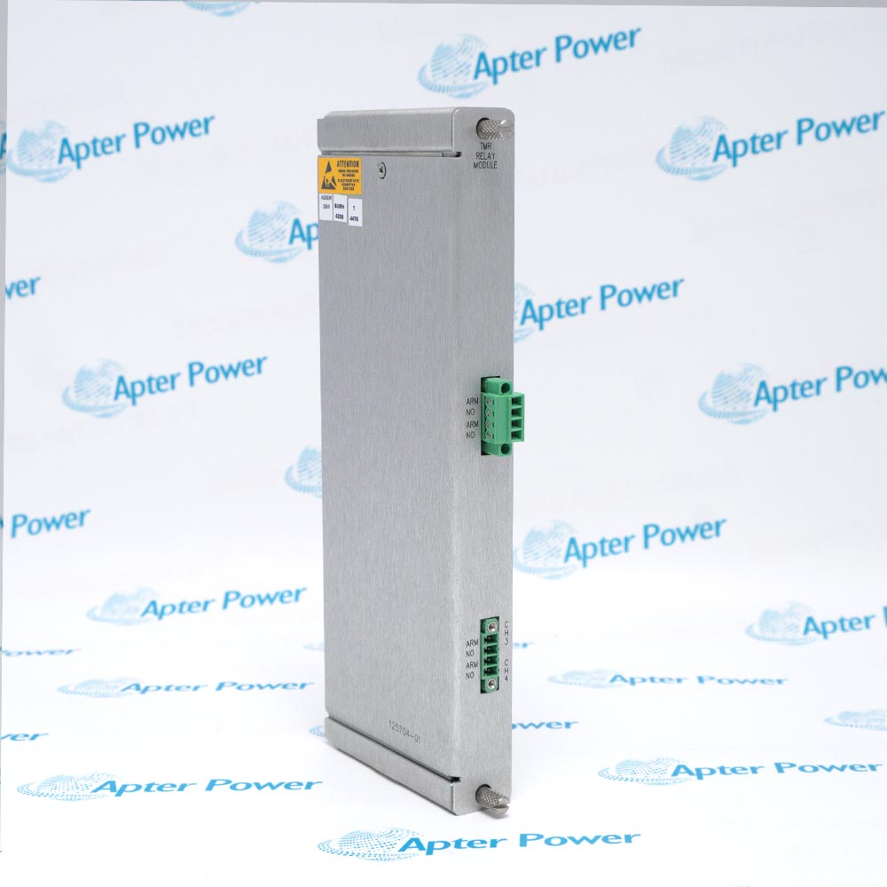
Product image is representative; revision or series may vary. Contact us to request a specific version.

Product Describe:

Bently Nevada 16710-35 is a 35 ft armored interconnection cable for a 177230 Seismic Transmitter loop.
  • Manufacturer part number
    16710-35
  • Shipping
    Swift global dispatch
  • Condition
    New, original product
  • Shipping size (est.)
    26cm x 26cm x 4cm
  • Country of Origin
    USA
Get a quick price for 16710-35
E-mail *
Mobile
Company
Content *
Quantity *
Upload (gif, jpg, jpeg, png, bmp, doc, docx, xls, xlsx, ppt, pdf, csv)
For more information on how your data is processed and stored by Apterpower please read our privacy policy

What happens after you enquire

  • 0

    Review your reference

    Send the full marking, quantity and label photos. We review the item and any version details that need clarification.
  • 1

    Confirm the offer

    Check the quoted reference, condition, included items and expected dispatch date before approving your order.
  • 2

    Arrange dispatch

    Confirm delivery details and receive the tracking number when it becomes available.
  • Match the complete marking

    Include 16710-35 and every revision or approval marking visible on the item. Keep the exact reference on your enquiry and quotation.
  • Check the offered item before ordering

    Request available label and interface photos. Have your maintenance team compare the offered 16710-35 reference with the installed equipment and applicable Bently Nevada documentation.

Technical specifications for 16710-35

  • Manufacturer:
    Bently Nevada
  • Product Category:
    Machinery Monitoring Systems
  • Spare Part Number:
    16710-35
  • Weight:
    0.86 kg
  • Tariff Code:
    8537101190
  • Cable function:
    177230 Seismic Transmitter interconnection
  • Selected length:
    35 ft (approximately 10.7 m)
  • Cable construction:
    With armor
  • Orderable length range:
    3 to 99 ft
  • Length increment:
    1 ft
  • Companion transmitter output:
    4 to 20 mA loop powered
  • Companion range options:
    0 to 12.7, 25.4 or 50.8 mm/s
  • Companion frequency options:
    10 Hz to 1 kHz RMS or 3 Hz to 1 kHz peak
  • Receiving systems:
    PLC, DCS or SCADA analog input
  • Identity boundary:
    Internal conductor and termination details must be verified from the delivered cable or approved drawing
  • Continuity boundary:
    Test only with the loop isolated
  • Acceptance check:
    Returned loop current and raw vibration signal compared with the machine baseline

Information

Overview Downloads Applications / Compatibility Product Precautions
  • Bently Nevada 16710-35 is a 35 ft armored interconnection cable for a 177230 Seismic Transmitter loop.
Selected cable: 35 ft armored interconnect for the 177230 Seismic Transmitter.
Ordering range: Custom lengths from 3 to 99 ft in 1 ft increments.
Signal context: Carries the loop-powered transmitter connection to the assigned PLC, DCS or SCADA input.
The 35 ft selection is an armored interconnect cable ordered for a 177230 Seismic Transmitter loop. Its length and routing must agree with the installed cable schedule and receiving input assignment.

The manufacturer ordering table identifies 16710 as the armored cable family but does not restate internal conductor colors or end terminations. Preserve the delivered construction exactly and verify both ends against the approved wiring drawing before removal.

Acceptance is an end-to-end loop task: inspect the armor and terminations, prove continuity with the loop isolated, then compare the returned 4 to 20 mA indication and raw vibration signal with the established machine baseline.
Platform: 177230 transmitter loop. Verify the installed chain.
Technical downloads for Bently Nevada 16710-35: model-specific technical reference and installation review.
Use the exact order code and installed configuration when applying either document.
System and supply context: The cable links the 177230 transmitter to its assigned control-system input; physical length, delivered terminations, routing and loop polarity govern application.

Platform applications: The uses below require the documented 177230 seismic-transmitter interconnect cabling companion components and approved machine drawing.
Prepare Bently Nevada 16710-35 using the approved machine documentation and site procedure.
Confirm the complete marking

Match 16710-35, cable length, connector and conductor construction with the installed record.

Isolate before testing

Place the monitor channel and machine in the approved maintenance state before disconnecting or checking continuity.

Protect the connector

Keep contacts dry and clean; do not use the connector or terminal lugs as a pulling point.

Support the route

Preserve bend clearance, armor support, abrasion protection and separation from damaging heat or sharp edges.

Verify conductor mapping

Label each conductor and shield before removal, then compare end-to-end continuity with the applicable wiring drawing.

Prove the complete channel

After reconnection, verify the expected monitor indication and operating response before return to service.

Alternative Names

Bently Nevada 16710-35 Bently Nevada 16710 35

Technical notes

Signal relationship: The cable connects the 177230 loop-powered seismic transmitter to the assigned PLC, DCS or SCADA analog input.

Ordering relationship: The 35 code selects a 35 ft armored cable within the documented 3 to 99 ft range.

Technical reference: Bently Nevada 177230 Seismic Transmitter Datasheet, 177232 Rev. U.

FAQ View All FAQ

  • Which transmitter context applies to 16710-35?
    Use the cable only where the installed record identifies a 177230 Seismic Transmitter and the assigned PLC, DCS or SCADA analog input.
  • How should the selected length of 16710-35 be verified?
    Confirm the 35 code and measure the delivered route against the specified 35 ft length before removing the installed cable.
  • What termination inspection is required for 16710-35?
    Compare both delivered terminations with the approved loop drawing and inspect contacts, insulation, strain relief and environmental sealing.
  • How should the armor of 16710-35 be treated?
    Support the armor independently, preserve the documented shield or drain termination and do not use armor as a signal return.
  • What continuity test is appropriate for 16710-35?
    With the transmitter loop isolated, test each documented path end to end and check for unintended conductor-to-shield or conductor-to-armor connections.
  • What routing evidence is needed for 16710-35?
    Record bend clearances, armor support, heat exposure, abrasion protection and separation from damaging power or process routes.
  • How is the loop proved after installing 16710-35?
    Reconnect according to the approved polarity and compare the 4 to 20 mA indication and raw vibration signal with the accepted machine baseline.
  • What handover data should accompany 16710-35?
    Retain the complete marking, physical length, termination map, continuity results, as-left route photographs and controlled loop-response result.
Manufacturers

Product Browsing History

Revisit the products you recently viewed on Apter Power.
SPEAK TO OUR TEAM
Let’s find the right solution for you.
Send us the part number, quantity and delivery destination. Our team will help confirm availability and lead time.
  • Whatsapp: +86 18030235313

    Send us a message.
  • sales13@apterpower.com

    Complete our online form.
  • +86 18030235313

    Speak to our team in your native language.