Speak to a sourcing specialist
sales13@apterpower.com

1746-HSCE

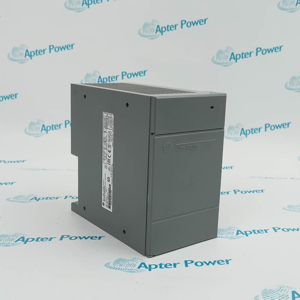
SLC 500 High-Speed Counter Module
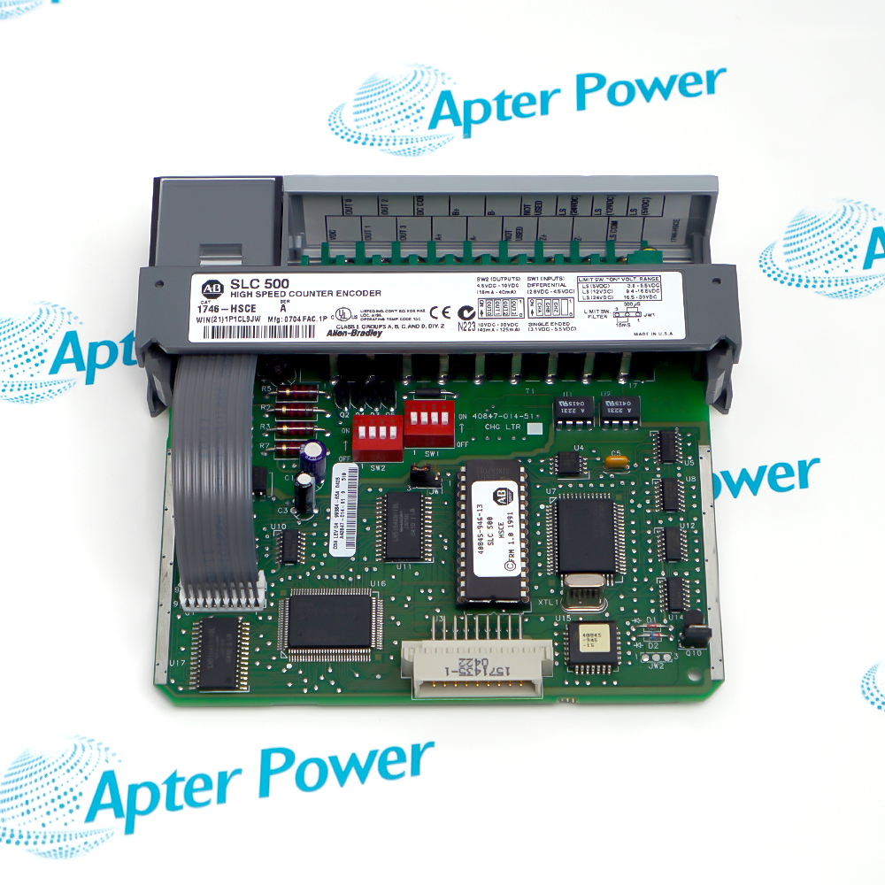
Allen-Bradley 1746-HSCE (1)
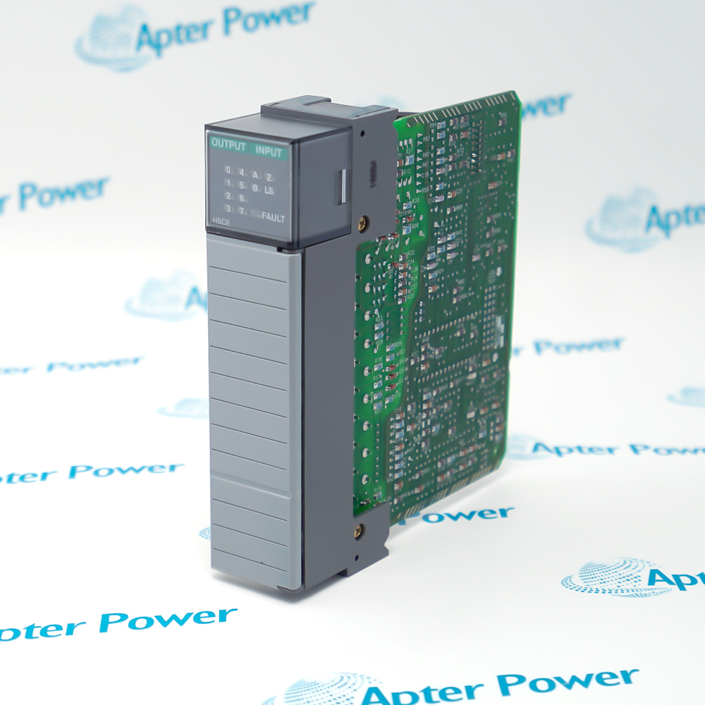
Allen-Bradley 1746-HSCE (2)
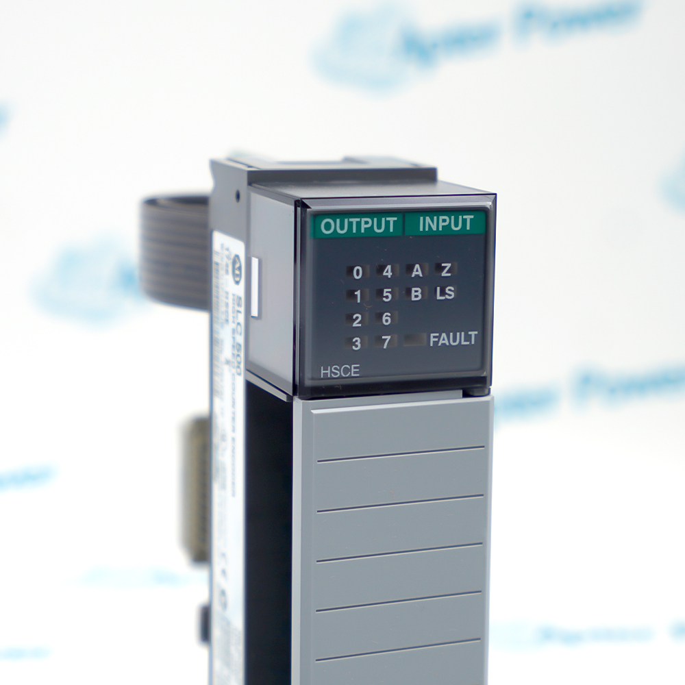
Allen-Bradley 1746-HSCE (3)
Allen-Bradley 1746-HSCE (1)
Allen-Bradley 1746-HSCE (2)
Allen-Bradley 1746-HSCE (3)
Product image is representative; revision or series may vary. Contact us to request a specific version.

Product Describe:

Allen-Bradley 1746-HSCE counts encoder and switch pulses in an SLC 500 chassis and controls local outputs against configured count or rate conditions.
  • Manufacturer part number
    1746-HSCE
  • Shipping
    Swift global dispatch
  • Condition
    New, original product
  • Shipping size (est.)
    3.5cm × 13cm × 14.5cm
  • Country of Origin
    USA
Get a quick price for 1746-HSCE
E-mail *
Mobile
Company
Content *
Quantity *
Upload (gif, jpg, jpeg, png, bmp, doc, docx, xls, xlsx, ppt, pdf, csv)
For more information on how your data is processed and stored by Apterpower please read our privacy policy

What happens after you enquire

  • 0

    Review your reference

    Send the full 1746-HSCE marking, chassis and processor details, plus the required quantity. We will review the intended counter module and interface.

  • 1

    Confirm the offer

    Review the available unit, terminal-block scope, condition and dispatch timing in the quotation.

  • 2

    Arrange dispatch

    Confirm the accepted quantity and delivery destination so the dispatch arrangements can be completed.

  • Match the complete marking

    Match the complete 1746-HSCE marking, series and terminal block to the installed SLC 500 assembly before ordering.
  • Check the offered item before ordering

    Request photos of the offered 1746-HSCE and have your maintenance team compare them with the installed module and the applicable Rockwell Automation high-speed counter documentation before ordering.

Technical specifications for 1746-HSCE

  • Manufacturer:
    Allen-Bradley
  • Product Category:
    PLC Systems
  • Spare Part Number:
    1746-HSCE
  • Weight:
    0.26 kg
  • Tariff Code:
    8537101190
  • Counter architecture:
    One bidirectional accumulated counter with rate measurement
  • Operating modes:
    Range, Rate and Sequencer
  • Encoder inputs:
    A, B and Z; differential or single-ended
  • Quadrature multipliers:
    ×2 and ×4
  • Maximum input frequency:
    50 kHz in Sequencer/Range; 32.767 kHz in Rate
  • Minimum pulse width:
    10 μs
  • Minimum phase separation:
    4.5 μs
  • Backplane current:
    320 mA at +5 V DC; 0 mA at +24 V DC
  • Output circuit:
    Four open-collector current-sinking outputs
  • Input-to-backplane isolation:
    1500 V
  • Operating temperature:
    0 to +60 °C
  • Humidity:
    5 to 95% RH, noncondensing
  • Maximum cable length:
    305 m with Belden 9503 or equivalent

Information

Overview Downloads Applications / Compatibility Product Precautions
  • A dedicated module captures motion pulses and updates its local outputs independently of the normal SLC program scan. The controller reads the module's status and accumulated value for the rest of the machine sequence.
Pulse decoding: A/B quadrature and a Z input for reference events
Output ownership: Local module or controller program
Setup interface: SLC module files and Function Control trigger
Select Range mode when the required action depends on count windows, Rate mode when pulse frequency is the controlling variable, or Sequencer mode when crossing preset values must advance an output pattern. Choose the mode from the machine's timing and reset behavior before assigning output ownership.

The Setup and Control Word in the M0 file selects the operation. The Function Control transition triggers the selected module function. A replacement therefore requires the original slot configuration and setup data in addition to matching the terminal wiring.

Use the module's indication and controller status together during commissioning. The input LEDs show field transitions, while the output LEDs show output state. Verify the machine sequence against the accumulated counter and the assigned output owner before enabling normal operation.
Controller platform reference: Allen-Bradley SLC 500 chassis I/O. Verify processor and slot configuration.
Find the operating modes and counter interface in the Rockwell technical excerpt. Use the separate Apter Power guide to plan field checks and commissioning.
Apply the manufacturer instructions and the site-approved control design for installation and maintenance.
Prepare Allen-Bradley 1746-HSCE using the applicable installation instructions and site isolation procedure.
Match the input interface

Check the encoder output type and configure the input selection for differential or single-ended wiring before connecting the field circuit.

Preserve quadrature polarity

Identify A and B at both ends of the cable. Test one known movement direction before releasing the system.

Verify reset filtering

Select the JW1 limit-switch filter for the mechanical switch response and the machine's reset timing.

Budget chassis current

Include the module's +5 V backplane demand in the chassis supply calculation, using the installed slot and other modules.

Use the correct output load

Treat the four outputs as sinking open-collector circuits. Check the external load supply, return and current before energizing.

Test without production loads

Prove count, reset and output behavior under controlled conditions. Reconnect the process only after the commissioning checks are complete.

Alternative Names

1746 HSCE Allen-Bradley 1746-HSCE

Technical notes

Input configuration: Select differential or single-ended A/B/Z connections to match the encoder, then compare the observed count direction with the machine reference.

Rate behavior: The rate measurement accumulates pulses over a configured period. Select the period to balance low-speed resolution against response time.

Technical reference: High-Speed Counter Module User Manual 1746-UM006B-EN-P and Installation Instructions 1746-IN011C-EN-P.


FAQ View All FAQ

  • How can I verify count direction after replacing a 1746-HSCE?
    Move the encoder slowly in the machine's defined positive direction and observe the accumulated count. If the sign is wrong, compare the A/B channel assignment and the configured count direction with the original wiring and program.
  • Can a 1746-HSCE be used behind a 1747-ASB remote I/O adapter?
    The 1746-HSCE user manual excludes the 1747-ASB. Confirm the actual chassis and processor arrangement before allocating a slot. The SLC form factor alone does not establish support.
  • How does the rate-period setting affect a 1746-HSCE application?
    A longer sampling interval captures more pulses at low speed and updates less often. Test both the slowest expected speed and the fastest acceptable response before finalizing the period.
  • What should I check if the 1746-HSCE counts but its physical outputs do not switch?
    Verify the selected output owner and active mode, compare the output LEDs and status to the expected pattern, then verify the external supply and return for the sinking load circuit.
  • How can I diagnose an unexpected counter reset on a 1746-HSCE?
    Review the enabled Z, limit switch and soft-reset sources. Compare their transitions and the configured reset action with the machine sequence, including the selected limit-switch filter.
  • What should be preserved from the SLC program when a 1746-HSCE is replaced?
    Keep the slot configuration, M-file mapping and setup/control data. Check that the intended Function Control transition occurs after the configuration words are ready.
  • How should the 1746-HSCE be commissioned when the encoder is already installed?
    Confirm the electrical input type and channel assignment first. Record the response to slow positive and negative motion, then exercise the configured reference input before testing the machine's normal sequence.
  • Why can an encoder signal look valid at low speed yet fail at full speed on a 1746-HSCE?
    Check pulse width and A/B phase separation at the actual field interface at operating speed. Verify the selected mode's frequency limit and the installed cable before changing program logic.
SPEAK TO OUR TEAM
Let’s find the right solution for you.
Send us the part number, quantity and delivery destination. Our team will help confirm availability and lead time.
  • Whatsapp: +86 18030235313

    Send us a message.
  • sales13@apterpower.com

    Complete our online form.
  • +86 18030235313

    Speak to our team in your native language.