Speak to a sourcing specialist
sales13@apterpower.com

1746-P1

SLC 500 Power Supply
In Stock
Ships by Saturday, November 21
Fast Shipping Available
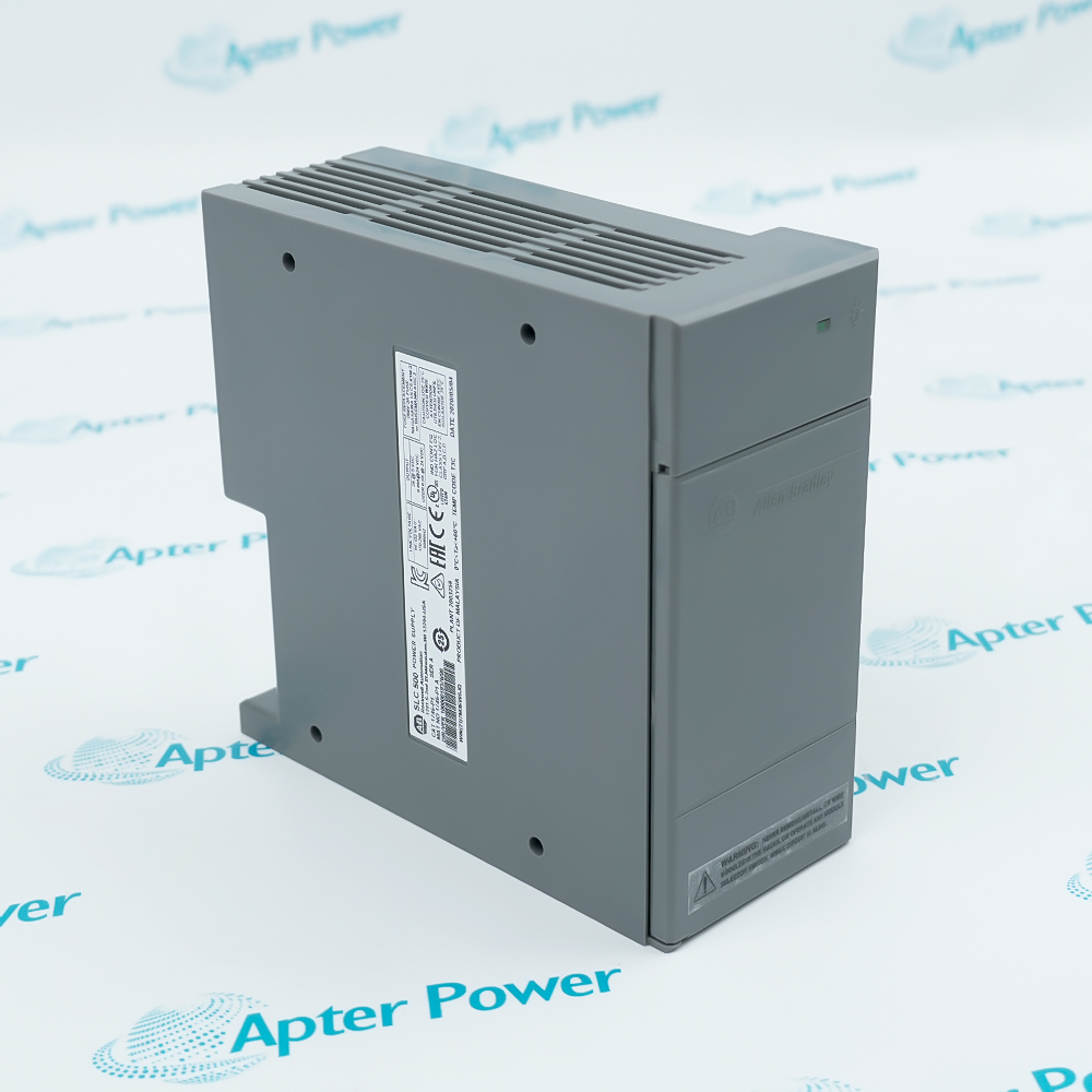
Allen-Bradley 1746-P1 SLC 500 power supply, angled view of grey housing with top vent grille and side label
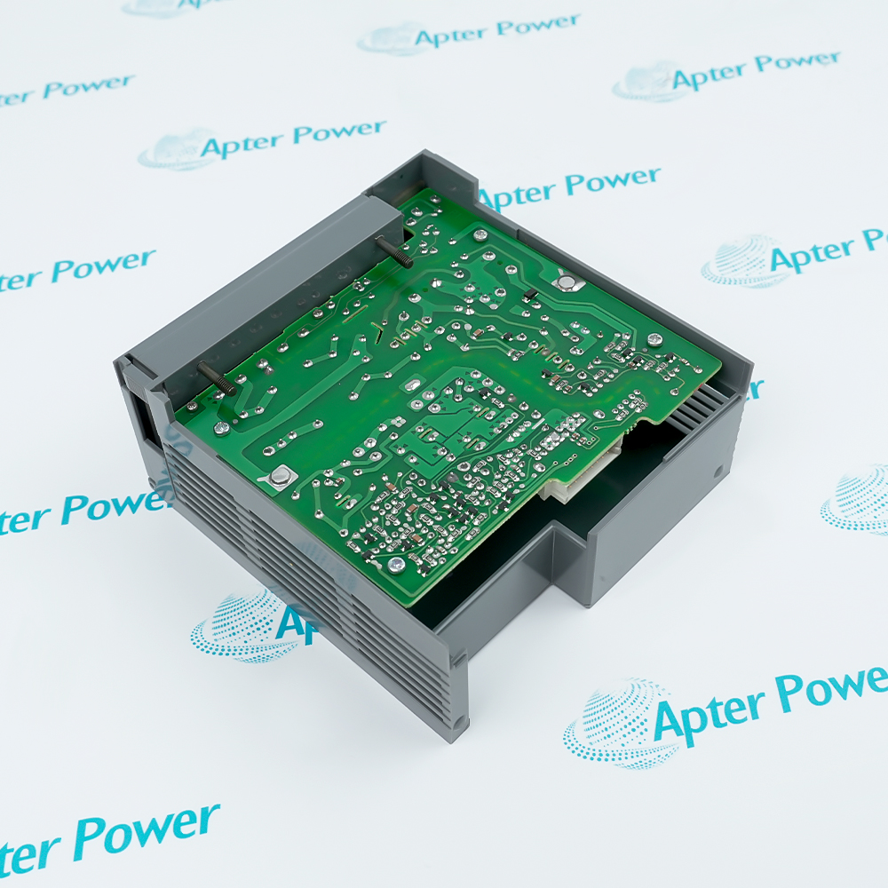
Allen-Bradley 1746-P1 power supply with cover removed, showing green circuit board and grey housing vent slots
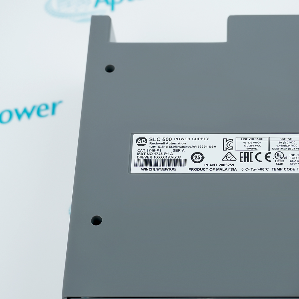
Allen-Bradley 1746-P1 SLC 500 power supply label close-up, CAT 1746-P1 SER A with 85-132 VAC and 170-265 VAC inputs
Allen-Bradley 1746-P1 SLC 500 power supply, angled view of grey housing with top vent grille and side label
Allen-Bradley 1746-P1 power supply with cover removed, showing green circuit board and grey housing vent slots
Allen-Bradley 1746-P1 SLC 500 power supply label close-up, CAT 1746-P1 SER A with 85-132 VAC and 170-265 VAC inputs
Product image is representative; revision or series may vary. Contact us to request a specific version.

Product Describe:

Allen-Bradley 1746-P1 is an SLC 500 chassis power supply with 120/240 V AC input, 2 A at 5 V DC backplane capacity, 0.46 A at 24 V DC backplane capacity and an isolated 24 V DC user output.
Get a quick price for 1746-P1
E-mail *
Mobile
Company
Content *
Quantity *
Upload (gif, jpg, jpeg, png, bmp, doc, docx, xls, xlsx, ppt, pdf, csv)
For more information on how your data is processed and stored by Apterpower please read our privacy policy

What happens after you enquire

  • 1

    Requirement review

    We review the part number, quantity and delivery requirements and ask for any missing details.
  • 2

    Quotation and availability

    We confirm the proposed item, condition, availability, price and estimated lead time in the quotation.
  • 3

    Order confirmation and dispatch

    Once the quotation and purchasing details are agreed, your contact will coordinate the order and available dispatch information.

Technical specifications for 1746-P1

  • Manufacturer:
    Allen-Bradley
  • Product Category:
    PLC Systems
  • Spare Part Number:
    1746-P1
  • Estimated shipping dimensions:
    6.5x14.3x14cm
  • Weight:
    0.45 kg
  • Tariff Code:
    8537101190
  • Counliy of origin:
    USA
  • Manufacturer:
    Allen-Bradley / Rockwell Automation
  • Product family:
    SLC 500
  • Product type:
    Chassis power supply
  • Line voltage:
    85-132 V AC or 170-265 V AC
  • Line frequency:
    47-63 Hz
  • Typical line power requirement:
    135 VA
  • Inrush current, maximum:
    20 A
  • Internal current capacity at 5 V DC:
    2 A
  • Internal current capacity at 24 V DC:
    0.46 A
  • 24 V DC user-power current capacity:
    200 mA
  • 24 V DC user-power voltage range:
    18-30 V DC
  • User-supplied overcurrent protection, maximum:
    15 A; time-delay type in ungrounded conductors
  • Input-to-backplane isolation:
    1800 V AC RMS for 1 second
  • CPU hold-up time:
    20 ms at full load; 3000 ms at no load
  • Ambient operating temperature:
    0-60 deg C (32-140 deg F)
  • Current-capacity derating:
    5% above 55 deg C (131 deg F)
  • Relative humidity:
    5-95%, noncondensing
  • Field wiring:
    No. 14 AWG (2 mm2)
  • Fuse protection:
    1746-F1 or equivalent 250 V, 3 A fuse
  • User-output construction:
    Isolated, non-fused 24 V DC output
  • Installation document:
    Rockwell Automation publication 1746-IN004B-EN-P

Information

Overview Manuals Common Applications Product Precautions
Allen-Bradley 1746-P1 is an SLC 500 chassis power supply with 120/240 V AC input, 2 A at 5 V DC backplane capacity, 0.46 A at 24 V DC backplane capacity and an isolated 24 V DC user output.
  • Supplies the SLC 500 chassis backplane from an 85-132 V AC or 170-265 V AC source
  • Provides 2 A at 5 V DC and 0.46 A at 24 V DC for backplane loading calculations
  • Provides an isolated, non-fused 200 mA user output at 24 V DC
  • Supports SLC 500 modular power planning with documented load and hold-up limits

Values are limited to Rockwell Automation publications 1746-IN004B-EN-P and 1747-SG001E-EN-E; final chassis loading and site protection remain installation-specific.

Important Notice: Confirm the complete 1746-P1 identity, installed-system configuration, approved isolation and functional acceptance record before service release.

Allen-Bradley 1746-P1 Manuals & Downloads
Allen-Bradley 1746-P1 Technical Reference (PDF)Allen-Bradley 1746-P1 SLC 500 Power Supplies Installation Instructions (PDF)

Important Notice: The first document is the model-specific technical reference. The second is Rockwell Automation's official installation instructions and is a separate document.


SLC 500 chassis power
Feeds the documented 5 V DC and 24 V DC backplane loads in an SLC 500 modular chassis.
24 V DC sensor supply
Provides the isolated 200 mA user output for approved low-current sensors and loads.
Machine-control cabinets
Supports SLC 500 controller and I/O assemblies after both backplane rails are checked.
Legacy SLC 500 maintenance
Provides a documented replacement path where the installed article is confirmed as 1746-P1.
Read the applicable Allen-Bradley installation instructions before work. Verify 1746-P1 and the installed-system configuration before commissioning.
1
Confirm the complete 1746-P1 nameplate and approved SLC 500 chassis position before removal.
2
Isolate incoming AC power and verify an electrically safe state before handling the power supply.
3
Verify that the line source is within 85-132 V AC or 170-265 V AC at 47-63 Hz.
4
Calculate the installed chassis demand against both the 2 A at 5 V DC and 0.46 A at 24 V DC limits.
5
Limit the isolated 24 V DC user output to 200 mA and monitor the circuit where required by the installation instructions.
6
Apply time-delay overcurrent protection in ungrounded conductors and preserve the specified fuse protection.
7
Use an isolation transformer where switching inductive loads can introduce damaging voltage surges.
8
Remove the protective label only after wiring is complete, then verify startup and the controlled I/O response before release.

Technical notes

Rockwell Automation SLC 500 Power Supplies Installation Instructions and SLC 500 System Selection Guide. Values are limited to publications 1746-IN004B-EN-P and 1747-SG001E-EN-E; final chassis loading and site protection remain installation-specific.

FAQ View All FAQ

  • What input supply does 1746-P1 accept?
    Rockwell Automation specifies 85-132 V AC or 170-265 V AC at 47-63 Hz.
  • What backplane current can this power supply provide?
    The documented internal capacities are 2 A at 5 V DC and 0.46 A at 24 V DC; both rails must be checked during power planning.
  • Does the unit provide a 24 V DC user output?
    Yes. The PWR OUT terminals provide an isolated, non-fused 200 mA output with a documented 18-30 V DC range.
  • What is the maximum inrush current?
    The official specification lists 20 A maximum inrush current for 1746-P1.
  • How does ambient temperature affect capacity?
    Operation is specified from 0 to 60 deg C, with current capacity derated by 5% above 55 deg C.
  • What hold-up time is documented?
    Rockwell lists 20 ms at full load and 3000 ms at no load; actual hold-up depends on power-supply loading.
  • Which fuse protection applies?
    The published protection is 1746-F1 or an equivalent 250 V, 3 A fuse; the fuse is intended primarily to guard against fire caused by short circuits.
  • What must be checked before returning the chassis to service?
    Verify identity, AC input, grounding, fuse and overcurrent protection, both backplane loads, user-output load, startup status and controlled I/O response.
SPEAK TO OUR TEAM
Let’s find the right solution for you.
Send us the part number, quantity and delivery destination. Our team will help confirm availability and lead time.
  • Whatsapp: +86 18030235313

    Send us a message.
  • sales13@apterpower.com

    Complete our online form.
  • +86 18030235313

    Speak to our team in your native language.