-
Match the complete marking
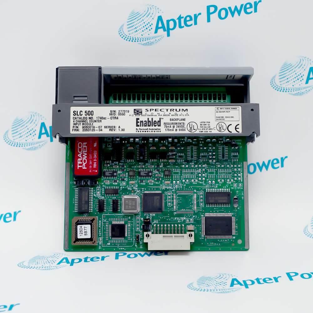
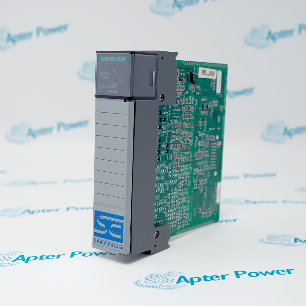
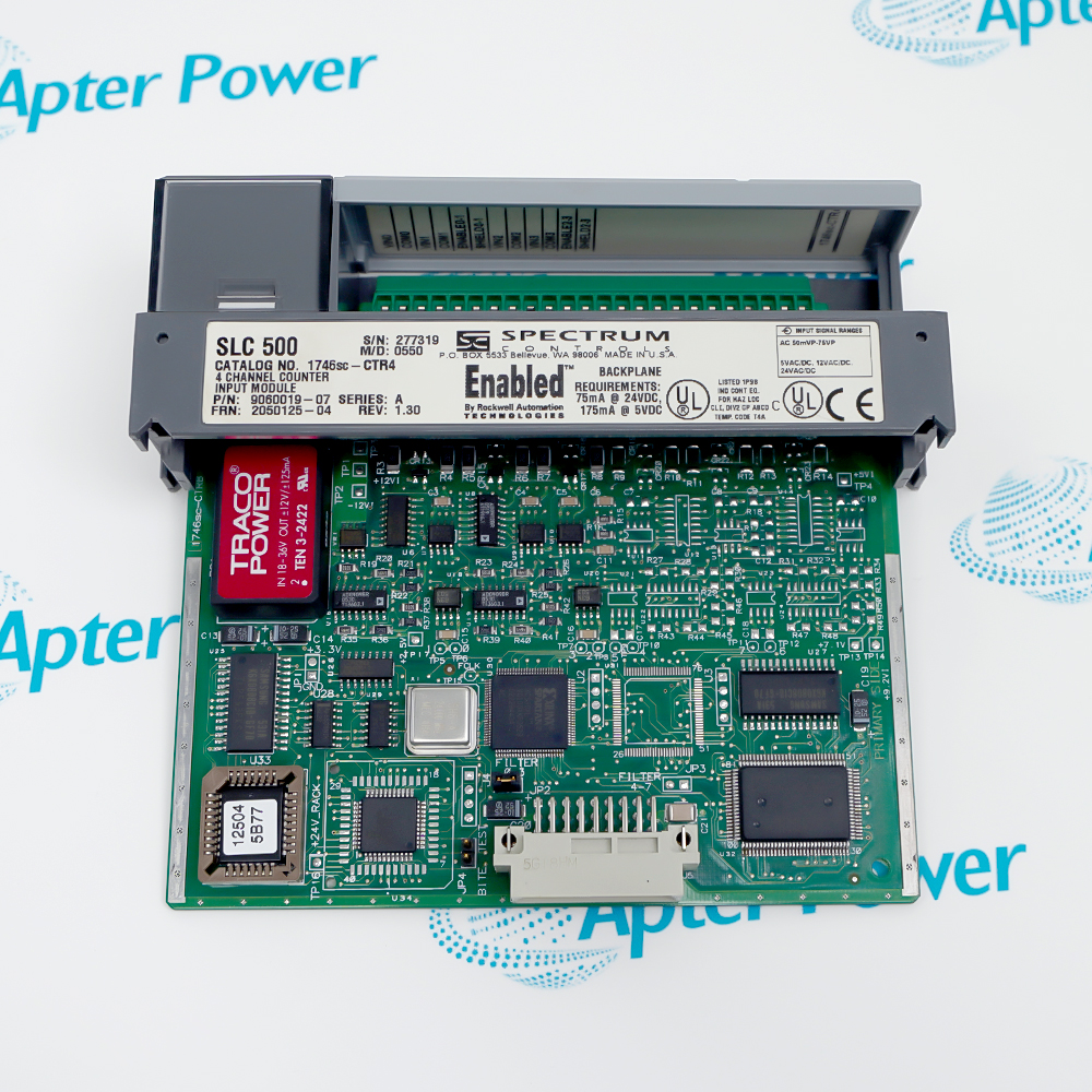
Match the complete Spectrum Controls 1746SC-CTR4 marking and the actual installed hardware configuration before approving the order. Check the Spectrum Controls label, CTR4 identity, terminal block, slot assignment and processor support.
-
Check the offered item before ordering
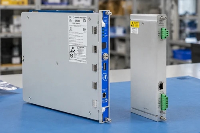
Request clear photographs of the offered 1746SC-CTR4 and ask your maintenance team to compare its markings and interfaces with the installed equipment and applicable Spectrum Controls instructions.
Technical specifications for 1746SC-CTR4
-
Manufacturer:Allen-Bradley
-
Product Category:PLC Systems
-
Spare Part Number:1746SC-CTR4
-
Weight:0.18 kg
-
Tariff Code:8537101190
-
Differential inputs:4
-
Quadrature channels:2
-
External enable inputs:2
-
Maximum input frequency:50 kHz
-
Selectable DC levels:5, 12 or 24 V DC
-
Module ID:10200
-
Image allocation:16 input and 16 output words
-
Rack current, 5 V:175 mA
-
Rack current, 24 V:75 mA
-
Isolation, channel to rack:1000 V DC
-
Isolation, channel to channel:None
-
Operating temperature:0-60 degrees C
Information
- Spectrum Controls 1746SC-CTR4 keeps pulse acquisition separate from the controller scan while configuration words determine how counts, direction and rate become application data.
Configuration: Class III image-table exchange
Application focus: Pulse qualification, scaling and overflow handling
The CTR4 reserves sixteen input and sixteen output registers and uses Class III operation. SLC 5/01 processors do not support that mode, and ASB remote-rack applications are unsuitable for this module because of its image size.
Input-level selection, filters, external enables and scaling factors determine the reported count or rate. Faster filtering does not repair poor pulse shape, and a correct raw count does not establish the application engineering-unit scale.
1746SC-CTR4 Original Technical Excerpt
Spectrum Controls SLC 500 Counter/Flowmeter Input Module User Manual, 0300181-09 Rev. A0. Selected original pages retain the applicable technical tables and interface context. PDF · 6 pages.1746SC-CTR4 Installation & Verification Guide
Apter Power field guide covering class iii allocation, pulse-source matching, filter and scaling setup, validation and handover. PDF · 5 pages.
Application scope: Select compatible companion hardware and retain the intended measurement or control function. Accessories are included only when itemized in the offered assembly.
Pulse accumulation
Count qualified pulses from a compatible DC source.Turbine-flow measurement
Convert the accepted pulse rate using the calibrated meter factor.Quadrature position feedback
Interpret paired pulse phases for direction and count.Rate supervision
Use configured rate, limit and status values in a compatible controller program.
Record processor type, slot, module ID and the sixteen-word input/output map. Back up configuration before disabling or removing the counter module.
Compare source level, pulse width, common-mode conditions and channel grouping. Verify quadrature pairing or external-enable wiring before applying a signal.
Restore the selected input filter, numeric range and K/M/R scaling. Keep raw pulse checks separate from the engineering-unit conversion.
Exercise enable, reset, preset and relevant alarm or overflow states using controlled input conditions. Include the selected rate-mode response in the test.
Compare module image data with the machine outcome, then remove test forcing and restore the approved operating sequence. Retain the final slot and channel records.
Retain the final 1746SC-CTR4 identity, wiring and verified configuration with the machine maintenance record.
Alternative Names
Technical notes
Processor compatibility: Use module ID 10200 with a processor that supports the required Class III image exchange. Do not use the CTR8 identity or assume compatibility with an SLC 5/01 or an ASB remote rack.
Timing and scaling: The count and instantaneous-rate update is 4.0 ms per channel with scaling off and 5.6 ms with scaling on. Average-rate mode updates at one second per channel; select the mode according to response and resolution requirements.
Isolation boundary: Channel-to-rack isolation does not provide channel-to-channel isolation. Review the field common-mode and grounding arrangement for all connected pulse sources.

FAQ View All FAQ
-
Why is 1746SC-CTR4 unsuitable for an SLC 5/01 processor?It requires Class III operation and a larger image exchange than the SLC 5/01 supports. A physical fit in the chassis does not establish processor compatibility.
-
Can 1746SC-CTR4 be placed behind an ASB remote-I/O adapter?The module is unsuitable for ASB remote-rack applications because of its input/output word requirement. Use a supported local architecture and confirm processor support.
-
What changes when 1746SC-CTR4 is switched from pulse counting to quadrature?Inputs are paired to interpret phase and direction, giving two quadrature channels. Recheck wiring, direction convention and channel allocation rather than retaining four independent input assumptions.
-
How can filtering on 1746SC-CTR4 cause missed pulses?A filter setting that rejects valid short pulses can reduce the accepted count. Choose the filter from signal frequency and pulse width, then validate it with representative waveforms.
-
Why does a correct raw count on 1746SC-CTR4 not prove the displayed flow rate?The conversion also depends on pulse-per-unit scaling and the selected rate mode. Check the source calibration and engineering-unit conversion independently of counting continuity.
-
How does enabling scaling change response time on 1746SC-CTR4?Count and instantaneous-rate update time increases from 4.0 to 5.6 ms per channel. Include that processing time and the controller update path in the response assessment.
-
Does the isolation rating of 1746SC-CTR4 isolate one pulse source from another?No. The specified isolation is between the input circuitry and rack; the channels are not isolated from each other. Review common-mode voltage and grounding across the field sources.
-
Why should rollover and overrange status be tested on 1746SC-CTR4?The application must interpret counts and flags correctly near the selected numeric limits. A short low-rate test can pass while overflow handling or sign interpretation remains wrong.
Supporting new and legacy automation
-
Please try to be as accurate as possible with your search.
-
We can quote you on 1000s of specialist parts, even if they are not listed on our website.
-
We can't find any results for “”.
Related cases and sourcing guidance
View all case studiesYou May Also Like
Product Browsing History
-
Whatsapp: +86 18030235313
Send us a message. -
sales13@apterpower.com
Complete our online form. -
+86 18030235313
Speak to our team in your native language.