Speak to a sourcing specialist
sales13@apterpower.com

1756-OF8

Eight-Channel Voltage and Current Analog Output Module
Allen-Bradley 1756-OF8
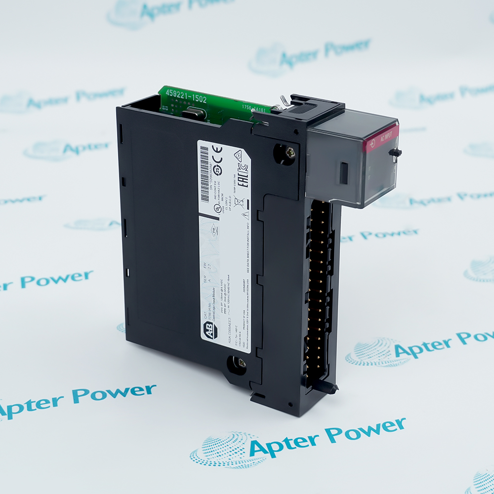
Product image is representative; revision or series may vary. Contact us to request a specific version.

Product Describe:

Allen-Bradley 1756-OF8 converts controller commands into eight voltage or current outputs in a ControlLogix chassis. The non-isolated output group uses a removable terminal block and supports configured output behavior during operating-state changes.
  • Manufacturer part number
    1756-OF8
  • Shipping
    Swift global dispatch
  • Condition
    New, original product
  • Shipping size (est.)
    23.3cm x 18.3cm x 5.3cm
  • Country of Origin
    USA
Get a quick price for 1756-OF8
E-mail *
Mobile
Company
Content *
Quantity *
Upload (gif, jpg, jpeg, png, bmp, doc, docx, xls, xlsx, ppt, pdf, csv)
For more information on how your data is processed and stored by Apterpower please read our privacy policy

What happens after you enquire

  • 0

    Review your reference

    Send the full 1756-OF8 reference, series label and the installed RTB and controller-project details.

  • 1

    Confirm the offer

    Review the offered series, firmware, condition and included terminal block against the installation.

  • 2

    Arrange dispatch

    Confirm quantity, delivery details and the agreed dispatch date before shipment arrangement.

  • Match the complete marking

    Include the full 1756-OF8 reference, hardware series, firmware label, RTB type and installed output configuration.

  • Check the offered item before ordering

    Request label and connector photographs. Have your maintenance team compare the offered 1756-OF8 with the installed module and applicable Rockwell Automation ControlLogix analog I/O instructions.

Technical specifications for 1756-OF8

  • Manufacturer:
    Allen-Bradley
  • Product Category:
    PLC Systems
  • Spare Part Number:
    1756-OF8
  • Weight:
    0.35 kg
  • Tariff Code:
    8537101190
  • Output channels:
    8 voltage or current
  • Selectable output ranges:
    ±10 V; 0–20 mA
  • Current resolution:
    15 bit across 21 mA; 650 nA/bit
  • Voltage resolution:
    15 bit across 10.4 V; 320 µV/bit
  • 5.1 V backplane current:
    150 mA
  • 24 V backplane current:
    210 mA
  • Backplane power:
    5.8 W
  • Voltage load:
    >2000 Ω
  • Current load:
    0–750 Ω
  • Resistive-load settling:
    <2 ms to 95% of final value
  • Calibrated accuracy at 25 °C:
    Better than 0.05% of range, 4–21 mA and −10.4 to +10.4 V
  • Typical calibration interval:
    12 months
  • Typical voltage offset drift:
    50 µV/°C
  • Typical current offset drift:
    0.1 µA/°C
  • Maximum voltage gain drift:
    25 ppm/°C
  • Maximum current gain drift:
    50 ppm/°C
  • Voltage module error:
    0.15% of range
  • Current module error:
    0.3% of range
  • Minimum scan, floating point:
    12 ms
  • Minimum scan, integer:
    8 ms
  • Output data formats:
    Integer; IEEE 32-bit floating point
  • Channel isolation:
    No individual output-channel isolation
  • Output-to-backplane insulation:
    250 V continuous, reinforced
  • Removable terminal blocks:
    1756-TBNH or 1756-TBSH
  • TBNH terminal torque:
    1.36 N·m
  • Operating ambient:
    0 to +60 °C
  • Storage temperature:
    −40 to +85 °C
  • Relative humidity:
    5–95%, non-condensing

Information

Overview Downloads Applications / Compatibility Product Precautions
  • Allen-Bradley 1756-OF8 links controller demand values to analog actuators and signal receivers. Correct operation depends on the selected data format, load circuit and transition behavior as well as the requested output magnitude.
Shared field reference: Internally connected returns require a coordinated grounding and load arrangement.
Controlled output changes: Configured initialization and transition behavior determine how demand is applied after a state change.
Diagnostic feedback: Output echo and channel status help compare the module command path with the field response.
Each channel must be connected to the appropriate voltage or current terminal and configured for the intended signal. The removable terminal block makes field wiring serviceable, but its common return structure does not provide individual channel isolation. Review load references before combining separately grounded equipment on the output group.

Communication format affects available functionality. In the Series A reference configuration, floating-point mode supports engineering-unit scaling, run-mode ramping and clamps with limit alarms. Integer mode retains selected program/fault transition and initialization functions but must not be assumed to offer every floating-point feature.

A command value, the module’s data echo and the physical actuator position represent different points in the control path. Commissioning must compare them under stable loading and during agreed program, fault and restart transitions. Hold-for-initialization can intentionally retain an output until the controller command matches the held value; this should be distinguished from a broken output circuit.
Controller platform reference: Allen-Bradley ControlLogix analog I/O. Confirm the supplied series, RTB and project configuration.
The files for Allen-Bradley 1756-OF8 separate original hardware and operating guidance from a commissioning workbook. View PDF provides a distinct engineering summary of output loading, scaling and state transitions.
Original manufacturer pages retain their technical context. Use the Apter Power guide with the applicable manufacturer instructions and approved installation design.
System and supply context: 1756-OF8 operates in a compatible ControlLogix chassis and controller project. The module, RTB and connected loads are separate parts of the installed circuit; included items must be identified in the quotation.

Application scope: The technical ratings here concern the Series A reference arrangement. Evaluate hardware-series and software-profile compatibility, signal loading and grounding before applying the module to a new or modified installation.
Prepare Allen-Bradley 1756-OF8 for its configured installation using these checks.
Confirm the offered series

Compare the actual module label and firmware with the installed project before relying on Series A reference values.

Map the RTB terminals

Trace each VOUT or IOUT circuit and the internally common RTN connections.

Check the complete load

Include receivers, indicators and cable resistance in a current-loop burden assessment.

Review the communication format

Confirm which ramping, scaling and clamp functions the selected data format supports.

Test state transitions safely

Check agreed program, fault, restart and initialization behavior under the approved maintenance state.

Verify the physical response

Compare commanded output, echo/status and the connected receiver before restoring automatic control.

Revisions

Revision Part #

Also known as

1756-OF8 Series A
1756-OF8/A; Series A reference shown in product photographs

Alternative Names

Allen-Bradley 1756-OF8 1756 OF8

Technical notes

Open-circuit detection: Detection applies to current operation and requires an output above 0.1 mA. A zero-current command is not a reliable open-wire proving condition.

Initialization hold: The Series A reference behavior holds the output until the commanded value matches the held terminal value within 0.1% of full scale. Inspect InHold when an output appears unresponsive after a transition.

Terminal practices: 1756-TBNH permits at most two appropriately sized conductors per terminal; 1756-TBSH uses a single conductor per terminal. Apply the selected RTB’s wire-size and temperature requirements.


FAQ View All FAQ

  • Why might 1756-OF8 retain its old output after a return to Run mode?
    Hold for Initialization may be active. Check the channel InHold status and reconcile the controller command with the held output within the specified matching tolerance before treating the condition as a hardware failure.
  • Can an open-wire test at a zero-current command validate 1756-OF8?
    No. Current-mode open-circuit detection needs an output above 0.1 mA. Use an approved nonzero test condition and verify both channel status and the actual field circuit.
  • Why can a command above a configured limit produce no further change on 1756-OF8?
    In a supported floating-point configuration, clamping holds the terminal output at the configured boundary and can assert a limit alarm. Compare the demand, clamp settings and alarm status before altering the field device.
  • Can run-mode ramping be retained when 1756-OF8 is changed from floating-point to integer format?
    The Series A reference supports run-mode ramping only in floating-point mode. Review the feature set before changing communication format; program/fault ramping is a separate behavior.
  • Does data echo from 1756-OF8 prove that an actuator reached its demanded position?
    No. Echo represents the module output data and associated status, not independent actuator travel. Compare terminal signal and separate position or process feedback where the application requires it.
  • How should an additional recorder be assessed in a current loop driven by 1756-OF8?
    Include the recorder’s burden and wiring resistance with the other series loads. The Series A reference current-load ceiling is 750 Ω; verify adequate total burden margin and correct wiring before inserting the device.
  • Can separately grounded receivers create unwanted interactions on 1756-OF8?
    Yes, the RTN terminals are connected internally and the channels are not individually isolated. Review reference potentials and grounding before combining circuits; backplane isolation does not establish channel-to-channel isolation.
  • Why can the end-to-end response of 1756-OF8 exceed its analog settling specification?
    The settling figure concerns the analog output’s response into a resistive load. Module scan, requested packet interval, controller execution, configured ramps and the field device can add delays; test the complete path.
SPEAK TO OUR TEAM
Let’s find the right solution for you.
Send us the part number, quantity and delivery destination. Our team will help confirm availability and lead time.
  • Whatsapp: +86 18030235313

    Send us a message.
  • sales13@apterpower.com

    Complete our online form.
  • +86 18030235313

    Speak to our team in your native language.