











Get Parts Quote
Name
Company *
Phone *
Email *
Address
City
State / Province / Region
Zipcode
Country
Quantity *
Part Number *
Manufacturer
Preferred Condition
Additional Information
Cancel
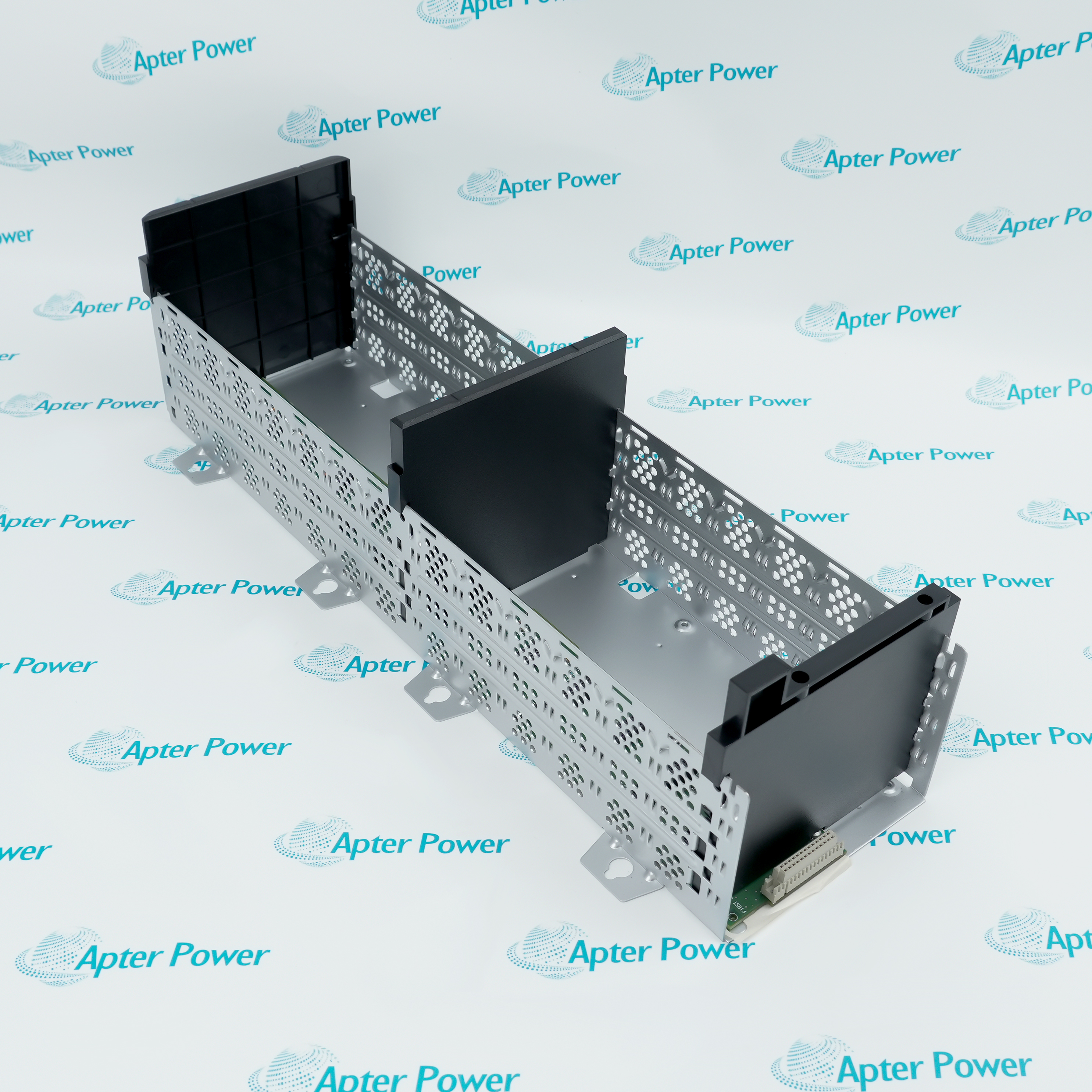
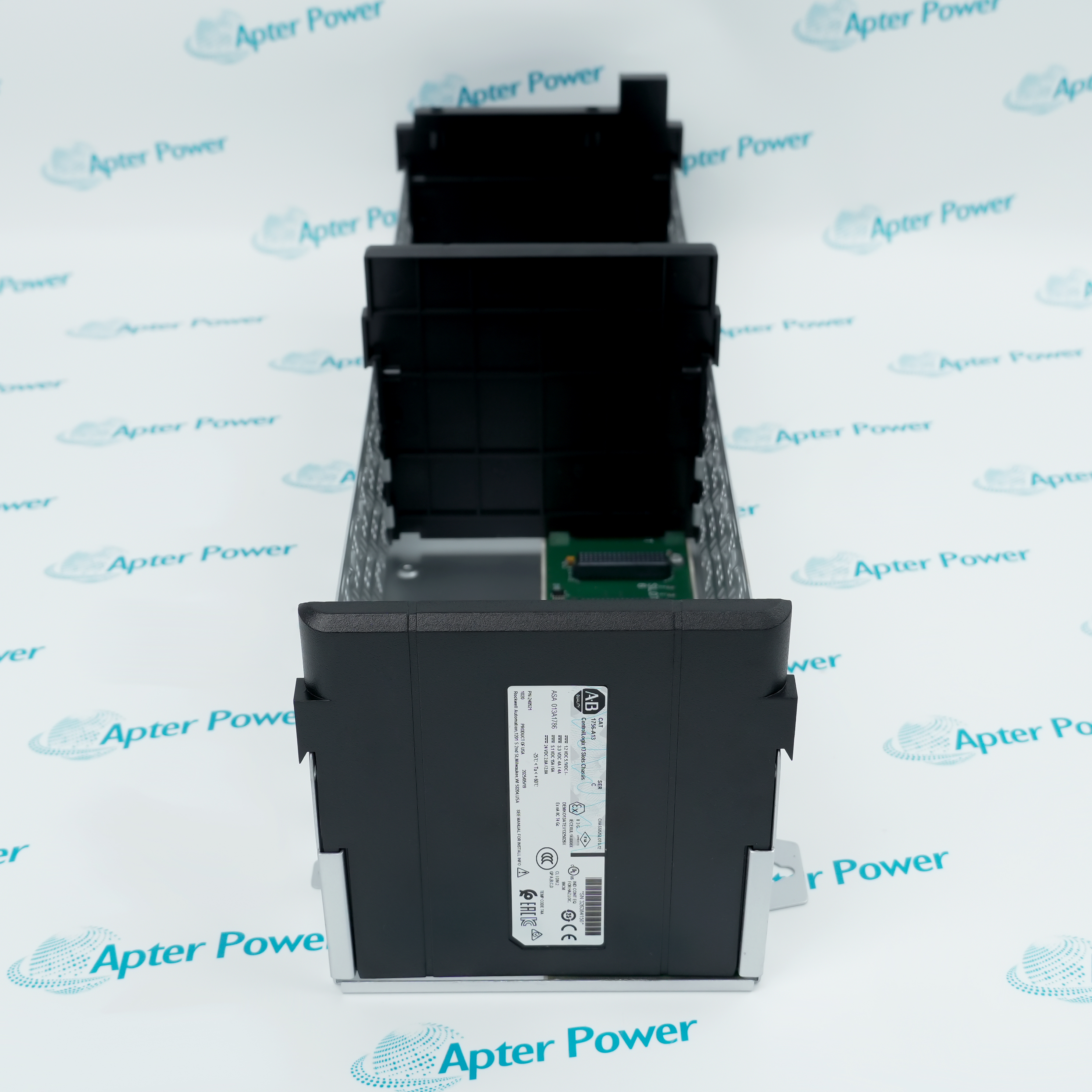
Allen-Bradley 1756-A13
Product image is representative; revision or series may vary. Contact us to request a specific version.

1756-A13

ControlLogix 13-slot Standard Chassis
In Stock

Product Describe:

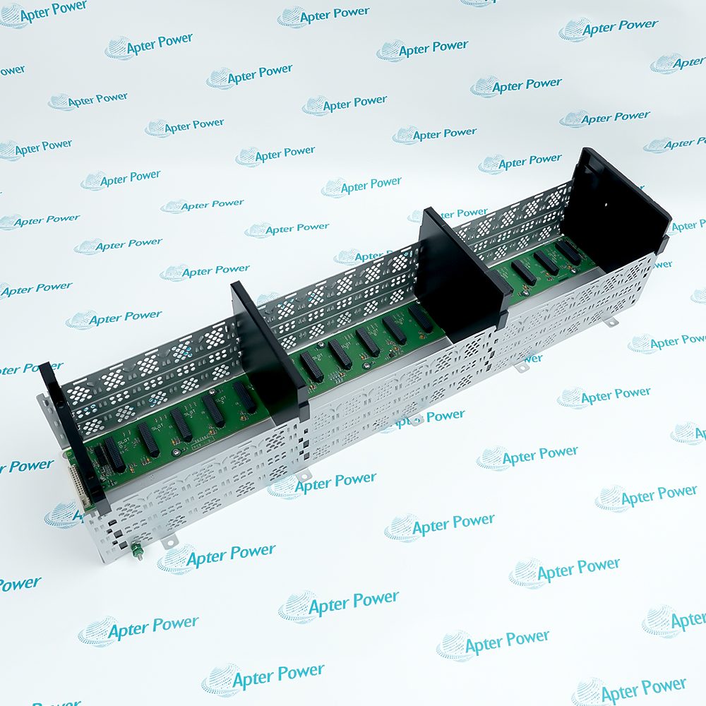
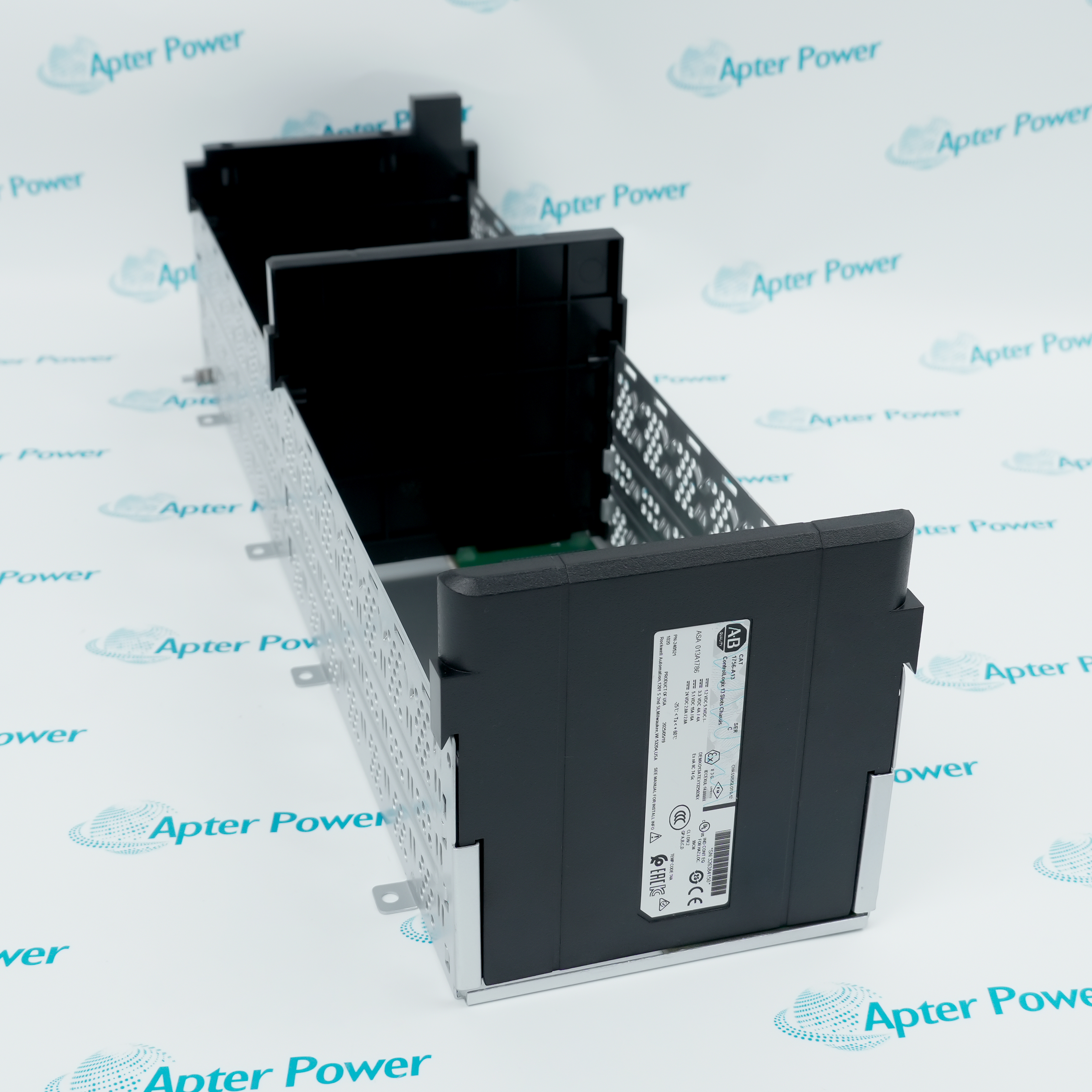
Allen-Bradley 1756-A13 is a 13-slot standard ControlLogix chassis. Its backplane provides the physical module positions, communication path and distributed operating power for an installed ControlLogix system.

Ask our team:

Get a quick price for: 1756-A13
Quantity*
Upload (gif, jpg, jpeg, png, bmp, doc, docx, xls, xlsx, ppt, pdf, csv)
For more information on how your data is processed and stored by Apterpower please read our privacy policy.

Technical specifications for 1756-A13

Technical specifications for 1756-A13

  • Manufacturer:
    Allen-Bradley
  • Product Category:
    PLC Systems
  • Spare Part Number:
    1756-A13
  • Estimated shipping dimensions:
    21.2x59x16.8cm
  • Weight:
    2.25 kg
  • Tariff Code:
    8537101190
  • Counliy of origin:
    USA
  • Chassis type:
    Standard ControlLogix
  • Module slots:
    13
  • Mounting:
    Horizontal back-panel
  • Enclosure type:
    Open style
  • Maximum power dissipation:
    5.4 W
  • Backplane current at 1.2 V DC:
    1.5 A chassis; 1.5 A per slot
  • Backplane current at 3.3 V DC:
    4 A chassis; 4 A per slot
  • Backplane current at 5.1 V DC:
    15 A chassis; 6 A per slot
  • Backplane current at 24 V DC:
    2.8 A chassis; 2.8 A per slot
  • Empty-slot filler:
    1756-N2
  • Series B operating temperature:
    0 to 60 deg C
  • Series C operating temperature:
    -25 to 60 deg C

Information

Information

Overview Manuals Common Applications Product Precautions
1756-A13 provides thirteen ControlLogix module positions on a powered high-speed backplane for a standard controller, communication and I/O assembly.
  • Provides thirteen standard ControlLogix module positions
  • Distributes supply rails through the chassis backplane
  • Carries module-to-module ControlBus communications
  • Supports a documented, serviceable controller and I/O assembly

The chassis is installed horizontally inside a suitable enclosure and accepts ControlLogix modules in the engineered slot plan. The installed supply must meet the combined 1.2 V, 3.3 V, 5.1 V and 24 V backplane load, while unused positions are closed with 1756-N2 fillers.

Important Notice: Confirm the full 1756-A13 marking, Series B or C environmental limits, horizontal mounting, enclosure, power supply, thirteen-position slot map, backplane loading, module hardware and firmware revisions, network configuration, grounding and controlled restart results before release.

Apter Power 1756-A13 Manuals and Guides

The first document is the model-specific technical and system reference. The second is a distinct field workbook for installation, wiring, commissioning and acceptance records.


Large ControlLogix controller stations
Provides the physical backplane for multi-module controller, network and I/O configurations.
Process-control rack expansion
Supports engineered combinations of communication and specialty modules in a standard enclosure.
Machine-control modernization
Provides a defined thirteen-slot platform when migrating a documented ControlLogix installation.
Redundant-system infrastructure
Houses the specific controller and communication arrangement selected by the approved project design.
Read the applicable Allen-Bradley installation instructions before work. Verify 1756-A13, the installed host system and all configured field interfaces before isolation, wiring or commissioning.
1
Confirm the complete 1756-A13 catalog number and chassis series.
2
Isolate the chassis supply and all connected field energy before work.
3
Photograph and record every occupied slot before removing modules.
4
Support the chassis and use only the documented horizontal mounting orientation.
5
Inspect the backplane connectors; do not touch contacts or force a module.
6
Recalculate every backplane rail against the installed power supply.
7
Install 1756-N2 fillers in all positions left unused by the project.
8
Restore power in a controlled sequence and verify all slot and network diagnostics.

Revisions

Revisions

Revision Part #

Also known as

1756-A13 Ser A
1756-A13/A, Series A, Rev A
1756-A13 Ser B
1756-A13/B, Series B, Rev B
1756-A13 Ser C
1756-A13/C, Series C, Rev C

Technical notes

Technical notes

Mount 1756-A13 horizontally on a rigid back panel and verify the chassis series, power-supply capacity and planned slot allocation before installation. Fit 1756-N2 fillers in unused positions and validate backplane recognition after any module exchange.

FAQS

  • What is the exact system role of 1756-A13?
    It is the thirteen-slot standard ControlLogix chassis that supports modules and distributes backplane power and communications.
  • Which host, rack or carrier is required for 1756-A13?
    Use it with a compatible standard ControlLogix power supply and the project-approved controller, communication and I/O modules.
  • What wiring or connector checks apply to 1756-A13?
    Disconnect power, preserve the slot map, inspect backplane connectors and confirm protective bonding before reconnecting the assembly.
  • How is 1756-A13 configured for service?
    The chassis itself has no application configuration; every installed module must be restored to its recorded slot and project configuration.
  • Which diagnostics should be reviewed for 1756-A13?
    Review power-supply status, controller major faults, slot recognition and communication-module diagnostics after startup.
  • What must be preserved when replacing 1756-A13?
    Preserve the chassis series, slot assignment, module revisions, keying and all network and project records.
  • How should 1756-A13 be commissioned after installation?
    Energize with outputs controlled, confirm every configured slot, then complete network and I/O proof tests.
  • What model-specific limitation must be checked for 1756-A13?
    Series B and Series C have different published operating-temperature limits, so the exact chassis series must be checked.
Trusted by 5,000+ plants worldwide | Backed by our vast inventory of top-tier control parts, modules and cards, fast shipments are dispatched to cover your urgent needs. ABOUT US >>
Disclaimer: We are not an authorized distributor or distributor of the product manufacturer of this website, The product may have older date codes or be an older series than that available direct from the factory or authorized dealers. Because our company is not an authorized distributor of this product, the Original Manufacturer`s warranty does not apply.While many DCS PLC products will have firmware already installed, Our company makes no representation as to whether a DSC PLC product will or will not have firmware and, if it does have firmware, whether the firmware is the revision level that you need for your application. Our company also makes no representations as to your ability or right to download or otherwise obtain firmware for the product from our company, its distributors, or any other source. Our company also makes no representations as to your right to install any such firmware on the product. Our company will not obtain or supply firmware on your behalf. It is your obligation to comply with the terms of any End-User License Agreement or similar document related to obtaining or installing firmware.

Product Browsing History

We’re Here When You Need Us

From product insights to customer service needs, our experienced service team will focus on getting you what you need quickly

Enquire

Complete our online form.

Call Us

Speak to one of our team.

Live Chat

Send us a message.
