-
Match the complete marking
Send the complete P0973BP marking, revision or option label, connector photographs and installed application details.
-
Check the offered item before ordering
Compare the offered P0973BP with the installed 156 w redundant power supply, termination hardware and approved Foxboro documentation before ordering.
Technical specifications for P0973BP
-
Manufacturer:Invensys
-
Product Category:DCS Systems
-
Spare Part Number:P0973BP
-
Weight:0.25 kg
-
Tariff Code:8537101190
-
AC input range:85–264 V AC
-
Input frequency:47–63 Hz
-
Continuous output:102 W or 156 W
-
Operating arrangement:Parallel redundant supply
-
Supply allocation:One unit per supported switch
-
Eight-position chassis:P0973BM
-
Two-position chassis:P0973BN
-
Operating temperature:5 to +40 °C
-
Relative humidity:5–90%, non-condensing
-
Storage temperature:-30 to +73 °C
-
Installation location:Ordinary locations
-
Contamination class:ISA S71.04 Class G1
Information
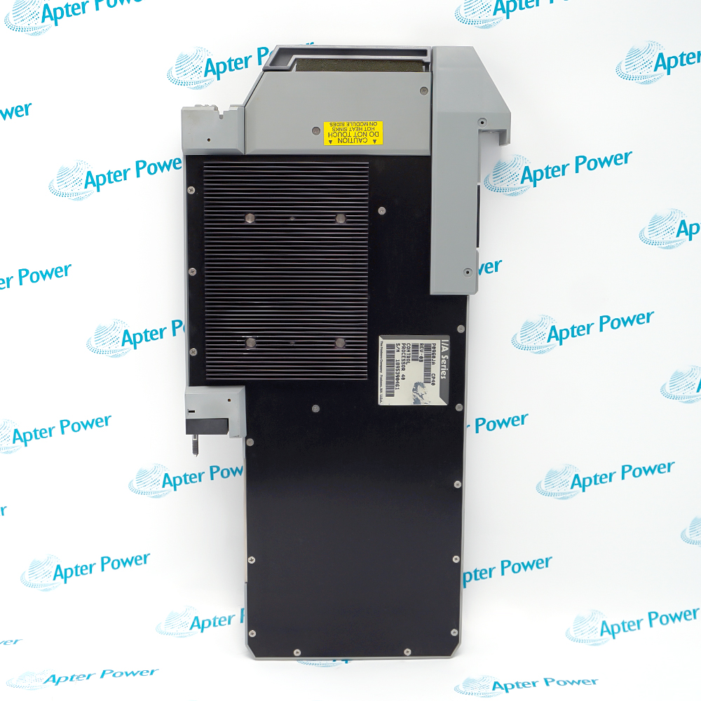
- Foxboro P0973BP is a 156 W redundant power supply used with the supported I/A Series switch-chassis arrangements.
Switch-chassis power continuity: Maintains the documented power architecture when one supported path is unavailable.
Chassis-specific service role: Applies to the approved switch and chassis combinations rather than as a general-purpose supply.
Use the verified technical rows below to screen the offer, then compare the installed drawing and manufacturer instructions. Rated output power: 156 W; Operating arrangement: Parallel redundant supply; Supply allocation: One unit per supported switch. These values do not authorize transferring specifications from a neighboring model.
During replacement, preserve the approved configuration and connection map. Perform a controlled visual, electrical and functional check, record the as-left result, and release the equipment only after the responsible site authority accepts the restored 156 w redundant power supply.
P0973BP Manufacturer Data Reference
Model-specific technical reference assembled from verified manufacturer-family records. PDF · 2 pages.P0973BP Installation & Verification Guide
Field guide covering identity capture, connection checks, controlled installation and acceptance evidence for P0973BP. PDF · 2 pages.
Application scope: Application suitability depends on the exact reference, hardware revision and installed configuration. Use site-approved drawings and manufacturer instructions for the final design decision.
Control-system power support
Use P0973BP only in the compatible I/A Series switch power subsystem arrangement identified by the approved system documentation.Redundant or protected supply service
Preserve the installed identity, connector orientation and configuration while restoring the documented function.Measured power verification
Use recorded as-found values and approved tests to distinguish connection, companion-hardware and product faults.Commissioning support
Keep the complete P0973BP reference and acceptance evidence with the asset record for future service.
Do not shorten P0973BP or transfer data from an adjacent reference.
Photograph connector orientation and label each cable or terminal before removal.
Retain the approved I/A Series switch power subsystem database, jumpers, switches or channel assignment as applicable.
Follow the site energy-isolation and ESD procedure before disturbing hardware.
Check the documented base, cable, terminal, power and partner-module relationship.
Complete visual, electrical and functional checks before return to automatic service.
Alternative Names
Technical notes
Evidence boundary: Technical rows apply to P0973BP or its explicitly identified manufacturer family context.
Compatibility: Physical fit does not establish electrical, firmware or system compatibility.
Commissioning: Use approved Foxboro instructions and site procedures for final installation and release.

FAQ View All FAQ
-
Which input and output values must be confirmed for P0973BP?Verify the nameplate input selection, frequency and documented DC output before connection; do not infer ratings from a similar supply.
-
How should the protective devices on P0973BP be handled?Use only the documented fuse or protective-device type and rating, and investigate the cause before replacement or reset.
-
Why is load margin important when commissioning P0973BP?The complete connected load, startup demand and redundancy arrangement must stay within the documented supply capability.
-
How should grounding be checked for P0973BP?Confirm protective earth, signal-reference arrangement and enclosure bonding against the approved system drawing before energization.
-
What should be recorded before removing P0973BP?Record terminal assignments, input selector position, connector orientation, status indications and measured input/output values.
-
Can P0973BP be energized without its normal load?Only when the manufacturer procedure and site method permit it; use a controlled test arrangement and observe output stability.
-
How should redundant operation involving P0973BP be proven?Test each supply path and transfer behavior under the approved maintenance condition without defeating required protection.
-
What as-left evidence is required for P0973BP?Retain input/output measurements, load current, protective-device status, alarm state and the responsible approval reference.
Supporting new and legacy automation
-
Please try to be as accurate as possible with your search.
-
We can quote you on 1000s of specialist parts, even if they are not listed on our website.
-
We can't find any results for “”.
Related cases and sourcing guidance
View all case studiesYou May Also Like
Product Browsing History
-
Whatsapp: +86 18030235313
Send us a message. -
sales13@apterpower.com
Complete our online form. -
+86 18030235313
Speak to our team in your native language.