Speak to a sourcing specialist
sales13@apterpower.com

FBM203 P0914SV

RTD Input Module
In Stock
Ships by Saturday, November 7
Fast Shipping Available
Product image is representative; revision or series may vary. Contact us to request a specific version.

Product Describe:

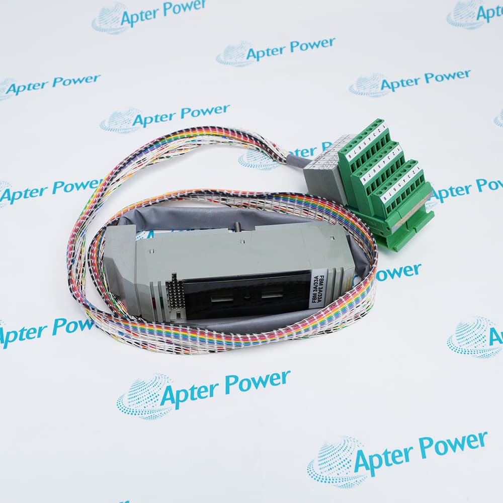
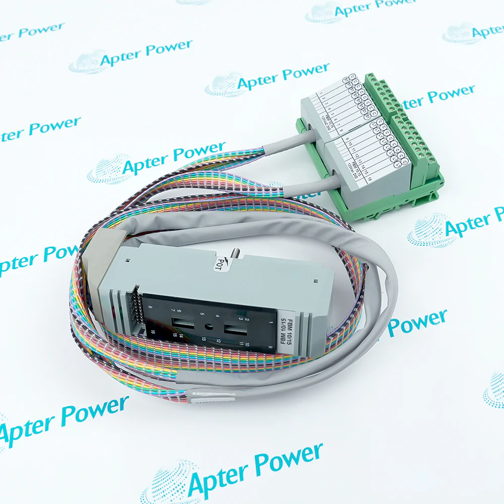
Foxboro FBM203 P0914SV is a rtd input module for resistance-temperature detector inputs. It operates with the RTD termination assembly and configured analog-input application and provides eight independent temperature channels.
Get a quick price for FBM203 P0914SV
E-mail *
Mobile *
Company
Content *
Quantity *
Upload (gif, jpg, jpeg, png, bmp, doc, docx, xls, xlsx, ppt, pdf, csv)
For more information on how your data is processed and stored by Apterpower please read our privacy policy

What happens after you enquire

  • 1

    Requirement review

    We review the part number, quantity and delivery requirements and ask for any missing details.
  • 2

    Quotation and availability

    We confirm the proposed item, condition, availability, price and estimated lead time in the quotation.
  • 3

    Order confirmation and dispatch

    Once the quotation and purchasing details are agreed, your contact will coordinate the order and available dispatch information.

Technical specifications for FBM203 P0914SV

  • Manufacturer:
    Invensys
  • Product Category:
    DCS Systems
  • Spare Part Number:
    FBM203 P0914SV
  • Estimated shipping dimensions:
    4.5x11x11.5cm
  • Weight:
    0.3 kg
  • Tariff Code:
    8537101190
  • Counliy of origin:
    USA
  • RTD channels:
    8 isolated inputs
  • Sensor wiring:
    2-wire or 3-wire RTDs
  • Resistance range:
    0 to 320 ohms
  • Supported elements:
    Platinum, nickel and copper RTDs
  • Fieldbus:
    Redundant 2 Mbps module Fieldbus

Information

Overview Manuals Common Applications Product Precautions
Foxboro FBM203 P0914SV accepts eight isolated platinum, nickel or copper RTD measurements and converts their resistance values for Foxboro control processing.
  • Provides eight independent temperature channels for its rtd input module function.
  • Handles resistance-temperature detector inputs through the documented Foxboro system path.
  • Works with the RTD termination assembly and configured analog-input application.
  • Independent conversion and isolation support channel-by-channel temperature acquisition.

The rtd input module belongs in the controlled Foxboro architecture and works with the RTD termination assembly and configured analog-input application. Its mating hardware, wiring, database configuration and final response must be checked together before release.

Important Notice: Use FBM203 P0914SV only with the RTD termination assembly and configured analog-input application; verify every interface and the controlled project configuration before energizing or pressurizing the subsystem.

Foxboro FBM203 P0914SV Manuals & Downloads
Foxboro FBM203 P0914SV Official Technical Reference Excerpt (PDF)Foxboro FBM203 P0914SV Installation & Commissioning Guide (PDF)

The first document covers the product function, system role and technical selection. The installation guide covers identification, connection checks, commissioning and the acceptance record.


System maintenance
Restores the documented rtd input module function in an existing Foxboro control system.
Signal-path service
Supports controlled testing of resistance-temperature detector inputs at the assigned system position.
Planned replacement
Provides an exact-identity replacement path after the RTD termination assembly and configured analog-input application has been verified.
Commissioning
Allows the responsible engineer to prove configuration, diagnostics and response for eight independent temperature channels.
Before installing Foxboro FBM203 P0914SV, confirm the documented system, interfaces and controlled configuration.
1
Match the complete FBM203 P0914SV marking to the work order and installed position before removal.
2
Confirm the RTD termination assembly and configured analog-input application before disconnecting any interface.
3
Keep resistance-temperature detector inputs within the documented electrical or pneumatic range.
4
Record terminal designations, polarity, common, shield and cable routing before disconnection.
5
Inspect mounting, connector keying, terminal condition and retention hardware before installation.
6
Restore the controlled database, range, alarm, filter and fail-state settings before energization.
7
Review local indicators and controller diagnostics during the controlled startup sequence.
8
Prove the intended response across eight independent temperature channels and record the acceptance result before release.

Technical notes

Use FBM203 P0914SV only with the RTD termination assembly and configured analog-input application; verify every interface and the controlled project configuration before energizing or pressurizing the subsystem.

FAQ View All FAQ

  • Which RTD materials are supported by Foxboro FBM203 P0914SV?
    The documented module family supports platinum, nickel and copper resistance-temperature detectors.
  • How many temperature channels does Foxboro FBM203 P0914SV provide?
    Eight isolated RTD input channels are available.
  • Which lead configurations can connect to Foxboro FBM203 P0914SV?
    The module accepts two-wire or three-wire RTD circuits.
  • What resistance span is associated with Foxboro FBM203 P0914SV?
    The documented input range is 0 to 320 ohms.
  • How should lead resistance be handled by Foxboro FBM203 P0914SV?
    Use the approved wiring mode and termination arrangement, then verify the configured compensation and measured value.
  • Which fieldbus carries measurements converted by Foxboro FBM203 P0914SV?
    Values are communicated over the redundant 2 Mbps module Fieldbus.
  • What should be tested after changing an RTD channel on Foxboro FBM203 P0914SV?
    Apply a known resistance or temperature reference and compare the channel value, diagnostics and alarm behavior.
  • Can Foxboro FBM203 P0914SV be replaced directly by an extended-range FBM203 variant?
    No. Confirm the complete part number, RTD range, sensor wiring and database configuration.
Related reading

Related cases and sourcing guidance

View all case studies
Manufacturers

Product Browsing History

Revisit the products you recently viewed on Apter Power.
SPEAK TO OUR TEAM
Let’s find the right solution for you.
Send us the part number, quantity and delivery destination. Our team will help confirm availability and lead time.
  • Whatsapp: +86 18030235313

    Send us a message.
  • sales13@apterpower.com

    Complete our online form.
  • +86 18030235313

    Speak to our team in your native language.