-
Match the complete marking
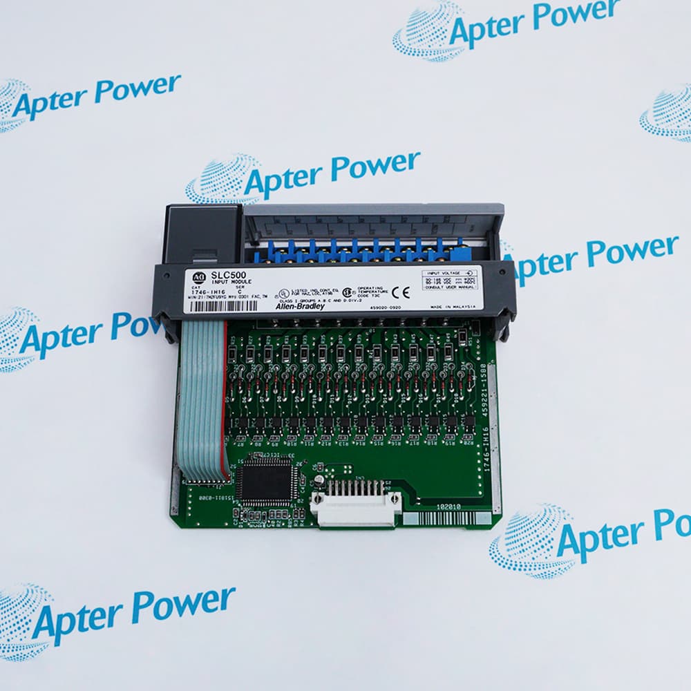
Include the complete 1746-NI16I marking, series and chassis slot. Retain the processor reference and configured interface class.
-
Check the offered item before ordering
Request label and terminal photographs. Have your maintenance team compare the offered 1746-NI16I with the installed equipment and applicable Allen-Bradley instructions.
Technical specifications for 1746-NI16I
-
Manufacturer:Allen-Bradley
-
Product Category:PLC Systems
-
Spare Part Number:1746NI16I
-
Weight:0.24 kg
-
Tariff Code:8537101190
-
Analog current inputs:16, single-ended
-
Selectable current ranges:±20 mA; 4–20 mA; 0–1 mA; 0–20 mA
-
Input impedance:249 Ω
-
A/D method:Sigma-delta
-
Converter arrangement:Four converters, each multiplexing four inputs
-
Filter selections:6, 10, 20, 40, 60, 80, 100 or 250 Hz
-
Input resolution:640 nA; data-format dependent
-
Engineering-unit increment:1 µA per count
-
Accuracy at 25 °C:Better than 0.15% of range
-
Error over 0–60 °C:±0.3%
-
Input offset drift:360 nA/°C
-
Gain drift:20 ppm/°C
-
Maximum input current:±30 mA between analog common and an input
-
Non-damaging signal voltage:±8 V between any two signal terminals
-
5 V backplane demand:125 mA
-
24 V backplane demand:75 mA
-
Maximum backplane power:2.425 W: 0.625 W at 5 V plus 1.8 W at 24 V
-
Class 1 module ID:3504
-
Class 3 module ID:10403
-
Class 1 I/O allocation:8 input words and 8 output words
-
Class 3 I/O allocation:32 input words and 32 output words
-
Class 3 measurement map:Data words 0–15; status words 16–31
-
Scaled-for-PID range:0–16383
-
Proportional-count range:−32768 to +32767
-
Custom scaling:Class 3 only
-
16-channel update at 40 Hz:100 ms with all enabled channels using 40 Hz
-
16-channel update at 250 Hz:18 ms with all enabled channels using 250 Hz
-
Open-circuit detection time:Less than 5 s on enabled 4–20 mA channels
-
Status indicators:Four green channel-group LEDs and one green module LED
-
Removable terminal block:1746-RT25G
-
Maximum terminal wire size:Two 14 AWG wires per terminal
-
Recommended signal cable:Belden 8761 or equivalent
-
Operating temperature:0 to +60 °C
-
Storage temperature:−40 to +85 °C
-
Relative humidity:5–95%, non-condensing
Information
- Allen-Bradley 1746-NI16I distributes acquisition across four analog-to-digital converters. How channels are assigned to these converters affects scan efficiency, while the selected interface class determines how the controller obtains measurements and diagnostic status.
Data interpretation: Range, format and interface class must agree with the controller logic.
Fault visibility: Channel status separates wiring and configuration problems from a valid process measurement.
Class 1 multiplexes channel data and status through an eight-word image. Class 3 makes sixteen data words and sixteen status words available together and permits user-defined scaling. The processor and network interface must support the selected class, and the application must not interpret a status word as an analog measurement.
Filter selection is shared by the four inputs on each converter. Only the selection in the first channel of each group controls that group. Distributing a reduced channel count across the four converters can improve update time, whereas merely disabling the last few channel numbers may leave the slowest converter workload unchanged.
1746-NI16I Official Technical Manual Excerpts
Original English identification, interface-class selection, conversion timing, current-loop wiring and technical ratings. PDF · 10 pages.1746-NI16I Installation & Verification Guide
Apter Power field guide for retaining the channel map, checking loop power, restoring class configuration and testing valid data and diagnostic behavior. PDF · 5 pages.
Application scope: Apply it to supported analog current sources with independently engineered loop power, common references and controller scaling. These examples do not establish voltage-input capability or channel-to-channel galvanic isolation.
Process transmitter acquisition
Acquire compatible 4–20 mA transmitters when the external supply has enough voltage compliance for the input burden, cable and other loop devices.Bipolar current measurement
Measure a supported ±20 mA signal with the correct polarity, range and signed data handling in the controller program.Multi-rate process groups
Assign channels with similar response and noise-rejection requirements to the same four-channel converter group.Existing SLC system service
Restore an installed current-input arrangement while retaining its module ID, image allocation, range configuration and status interpretation.
Remove chassis and external loop power before inserting the module or changing terminal connections.
Identify the internally connected analog commons and prevent unintended cross-connections to chassis or unrelated supplies.
Use the correct removable terminal block, inspect its keying and keep unused input terminals connected to analog common as instructed.
Match the input type, data format, enable state and interface class to the retained controller project.
Set filter choices in channels 0, 4, 8 and 12 for their respective four-channel converter groups.
Inject known currents, inspect data and status together, and test an approved broken-loop case before returning to process control.
Alternative Names
Technical notes
Loop burden: A 249 Ω input produces a calculated 4.98 V drop at 20 mA. Add transmitter headroom, wire resistance and other series devices when checking the external supply; the input burden alone is not the complete loop load.
Shared filtering: The first channel of each converter group owns its filter selection. Entering a different filter for another channel in that group does not give it an independent acquisition filter.
Valid data: A channel data word is valid only when the channel is enabled and free of channel errors. Reading a numerically plausible value without its corresponding status can conceal a failed circuit.
Open-loop diagnosis: Open-circuit monitoring applies to enabled 4–20 mA channels. A detected open loop returns 0 mA and a channel fault; a zero reading on a 0–20 mA range does not by itself distinguish an open wire from a valid zero signal.

FAQ View All FAQ
-
Why can changing the filter on channel 2 of 1746-NI16I leave its response unchanged?Channel 2 shares a converter with channels 0–3. The filter configured in channel 0 governs that group. Check the first-channel setting and then measure the response under the actual enabled-channel pattern.
-
Will disabling channels 12–15 automatically make 1746-NI16I update 25% faster?No. The remaining converter groups may still scan four inputs each. For a twelve-channel arrangement, distribute three enabled channels per converter, such as 0–2, 4–6, 8–10 and 12–14; verify the resulting timing in the controller.
-
What could make a healthy 20 mA transmitter saturate below full scale on 1746-NI16I?The loop supply may lack compliance voltage. The 249 Ω module input alone drops 4.98 V at 20 mA. Check transmitter headroom, cable drop and other series loads with the actual current flowing before changing the scale.
-
Can a zero value on a 0–20 mA channel of 1746-NI16I prove that its wire is intact?No. Zero is a valid endpoint of that range and the current-input open-circuit feature applies to 4–20 mA operation. Use an approved loop continuity or injected-signal test and inspect the channel status.
-
Why might an SLC program read alternating values and status through 1746-NI16I?Class 1 uses configuration control bits to select channel bank and whether the returned words contain data or status. Verify the handshake and interpretation before treating every input word as a continuous measurement.
-
Can an SLC 5/01 use the Class 3 image of 1746-NI16I?No. SLC fixed and SLC 5/01 processors use Class 1. Check the actual processor and remote adapter before allocating a Class 3 image or importing logic written for another host.
-
Why does clearing the enable bit on 1746-NI16I not prove that a channel fault was repaired?Disabling a channel resets its status information. Restore the correct configuration, re-enable the channel and allow it to process the configuration before checking whether the underlying fault has cleared.
-
How should a current injection test of 1746-NI16I distinguish scaling errors from wiring errors?First compare the injected current with the configured current range and returned data format. If the raw value is correct but the engineering value is wrong, review conversion logic. If the raw value or status is wrong, check the loop, common, channel enable and configuration.
Supporting new and legacy automation
-
Please try to be as accurate as possible with your search.
-
We can quote you on 1000s of specialist parts, even if they are not listed on our website.
-
We can't find any results for “”.
Related cases and sourcing guidance
View all case studiesYou May Also Like
Product Browsing History
-
Whatsapp: +86 18030235313
Send us a message. -
sales13@apterpower.com
Complete our online form. -
+86 18030235313
Speak to our team in your native language.