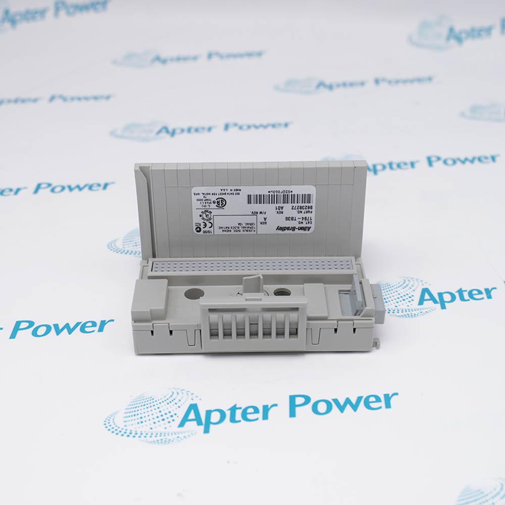
-
Match the complete marking
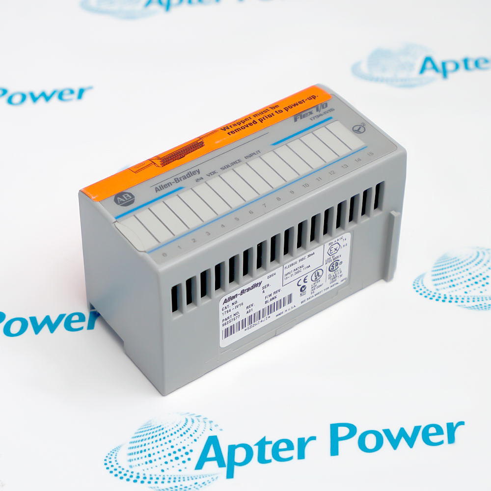
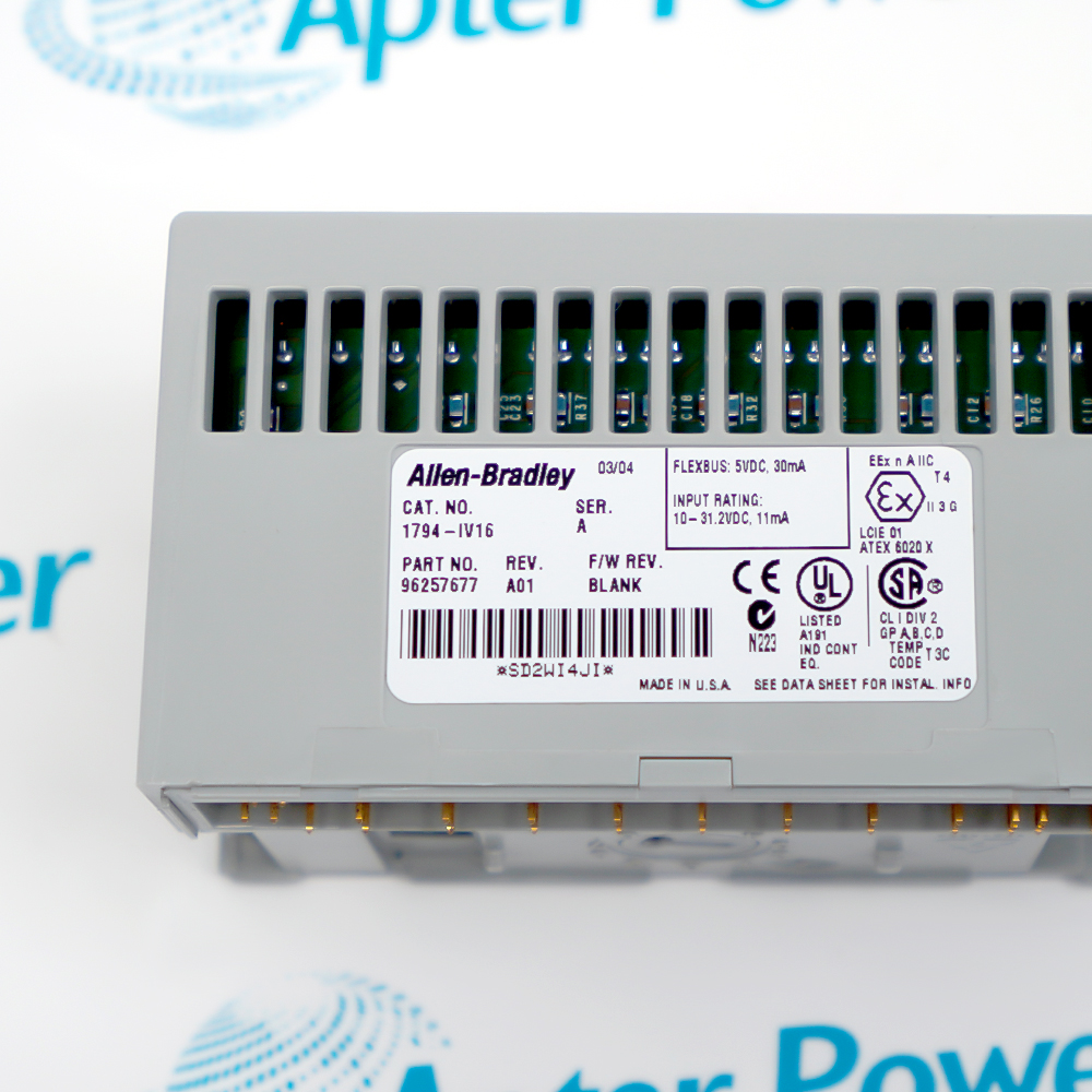
Match the complete 1794-IV16 marking and series, compatible terminal base, and installed adapter before ordering.
-
Check the offered item before ordering
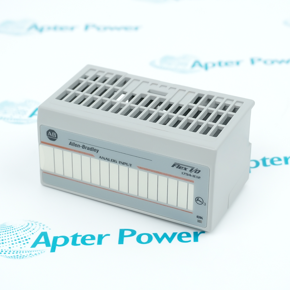
Request photos of the offered 1794-IV16 and have your maintenance team compare them with the installed module and applicable Rockwell Automation FLEX I/O documentation before ordering.
Technical specifications for 1794-IV16
-
Manufacturer:Allen-Bradley
-
Product Category:PLC Systems
-
Spare Part Number:1794-IV16
-
Weight:0.1 kg
-
Tariff Code:8537101190
-
Input channels:16 nonisolated sourcing DC inputs
-
Nominal input voltage:24 V DC
-
On-state voltage:10 to 31.2 V DC
-
Off-state voltage:5 V DC maximum
-
On-state current:8 mA nominal at 24 V DC; 2 to 11 mA range
-
Input filter:0.25, 0.5, 1, 2, 4, 8, 16 or 32 ms; 0.25 ms default
-
Filter configuration:Configuration word 3, bits 08–10; applies to inputs 0–15
-
Input image:Read word 0 contains I0–I15
-
Counter option:Input 15 counter value in read word 1; adapter-dependent
-
Flexbus current:30 mA
-
Input isolation:2121 V DC for 1 s between user and system; no channel-to-channel isolation
-
Status indicators:16 yellow field-side input indicators
-
Terminal bases:1794-TB3, 1794-TB3K, 1794-TB3S or 1794-TB3SK
-
Enclosure type:Open-style equipment; suitable cabinet required
-
Operating temperature:−20 to +55 °C, subject to supply and mounting derating
Information
- The 1794-IV16 occupies a FLEX I/O terminal base and presents 16 field input states to the adapter. Terminal wiring, input filtering and adapter type together determine what the controller observes.
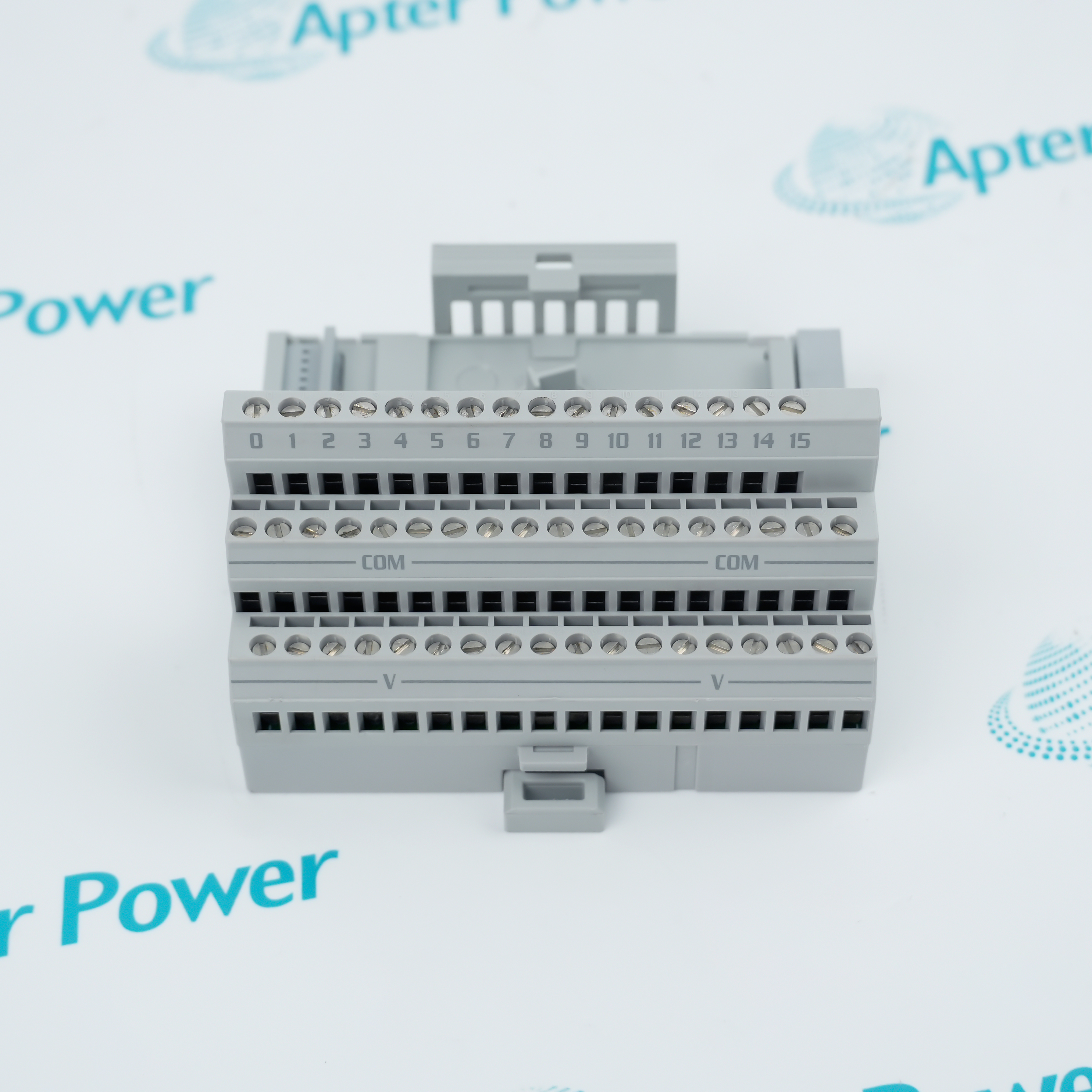
Field termination: Input A row, common B row and optional device power C row
Controller view: Read word 0 maps input channels 0–15
All 16 input bits enter the adapter's input image. Configuration word 3 selects one filter time for the input group, so a longer setting can suppress brief transitions but delays recognition of valid changes. Select the setting against the process pulse length and the controller scan behavior, then test both rising and falling events.
Input 15 also has a counter-related value and fast/filtered selection in the documented image map. Those counter controls are unavailable with any series 1794-ASB or 1794-ASB2 remote I/O adapter. Verify the installed adapter and program image before reusing a configuration that depends on those fields.
-
1794-IV16 Technical Reference
Rockwell Automation excerpt · PDF, 5 pages. 1794-IV16 input wiring, operating limits and terminal-base context. -
1794-IV16 Installation & Commissioning Guide
Apter Power guide · PDF, 4 pages. Wiring map, configurable filter, commissioning checks and fault isolation.
Platform applications: Use the channel image for discrete machine states; assess filter timing and adapter-dependent counter features separately from ordinary on/off sensing.
-
Discrete device collection
Bring sixteen compatible DC field signals into one FLEX I/O station. Group related input tags so the field terminal, input bit and process state can be tested together. -
Two-wire and three-wire devices
Wire a two-wire device to input and common, or provide the corresponding C-row power terminal for a three-wire device on the documented terminal bases. -
Noise-sensitive signals
Apply the shortest filter that rejects measured interference while passing the shortest valid process event. Check both change directions under operating conditions. -
Input 15 event counting
Use the documented counter/fast-data path only after confirming adapter support; 1794-ASB and 1794-ASB2 arrangements do not expose those controls.
De-energize the adapter/backplane and field supply before handling the module or terminal base. Confirm the area is nonhazardous where applicable.
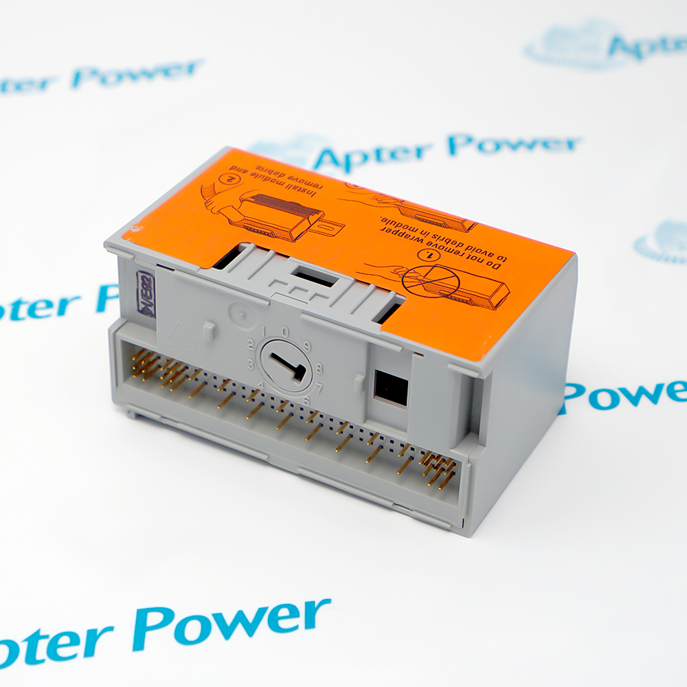
Compare the installed base catalog, keyed position and fully extended Flexbus connector with the module before seating it.
Trace the signal, common and optional device-power conductor for every used channel; do not apply output-module wiring from the shared publication.
Include all devices fed through the base in the terminal-base current calculation; provide separate supply connections if the 10 A limit would be exceeded.
Compare actual field supply voltage, cabinet temperature and mounting orientation with the manufacturer's derating curve before release.
Toggle representative short and sustained inputs with loads safely inhibited, and compare LEDs, input-image bits and configured filter response.
Alternative Names
Technical notes
Wiring relationship: The 1794-IV16 connects a sourcing field input to its A-row signal and B-row common. C-row device power applies to the documented three-wire arrangement.
Adapter boundary: Counter-related controls for input 15 are unavailable with 1794-ASB and 1794-ASB2 remote I/O adapters; ordinary input bits remain a separate configuration question.
Technical reference: FLEX I/O Digital Sourcing Input and Sinking Output Modules Installation Instructions, 1794-IN095D-EN-P, March 2024.

FAQ View All FAQ
-
How should I map a three-wire sensor to a 1794-IV16 input?Use the selected channel's A-row signal, corresponding B-row common and corresponding C-row power terminal on a documented 1794-TB3/TB3S arrangement. Trace each lead against the sensor's actual wiring diagram, then prove the channel LED and input bit before releasing the machine.
-
Why can a 1794-IV16 LED change while the controller bit appears stable?Check the adapter input image and selected filter time. A pulse shorter than the configured filter period may not become a recognized state; compare the physical LED transition, image bit and actual pulse width under controlled operation.
-
How do I select the 1794-IV16 input filter for a short event?Measure the shortest valid on and off durations and the observed noise. Choose a filter value that still recognizes the valid event, then test both directions at the fastest process cycle rather than assuming the default is suitable.
-
Can the 1794-IV16 input 15 counter be used with a 1794-ASB adapter?The documented counter, reset and fast-data controls are unavailable with any series 1794-ASB or 1794-ASB2 remote I/O adapter. Verify the adapter marking and program image before selecting a counting design.
-
What should I inspect if only one 1794-IV16 channel fails?Compare the failing channel's A-row signal and B-row common with a known working channel, including the field device and cable. Check its LED and input-image bit separately; do not bridge an unverified supply into the input.
-
What changes when replacing a 1794-IV16 with another FLEX input type?Check sourcing versus sinking direction, accepted voltage, terminal-base wiring, input-image mapping and filter behavior. Keep the existing program and field drawings as the acceptance reference; a matching channel count alone does not establish compatibility.
-
How can I confirm a 1794-IV16 is seated correctly after maintenance?With power isolated, confirm straight connector pins, keying, aligned groove and a latched module on the compatible terminal base. Restore power under site procedure, then verify adapter recognition and representative input indications.
-
How should I test a 1794-IV16 after changing its filter setting?Record the original configuration word, apply the selected timing, and exercise the shortest real input event plus a sustained state. Compare field waveform, LED, controller image and process response; restore the approved setting if recognition is lost.
Supporting new and legacy automation
-
Please try to be as accurate as possible with your search.
-
We can quote you on 1000s of specialist parts, even if they are not listed on our website.
-
We can't find any results for “”.
Related cases and sourcing guidance
View all case studiesYou May Also Like
Product Browsing History
-
Whatsapp: +86 18030235313
Send us a message. -
sales13@apterpower.com
Complete our online form. -
+86 18030235313
Speak to our team in your native language.