Speak to a sourcing specialist
sales13@apterpower.com

330500-04-01

Velomitor piezo-velocity sensor
In Stock
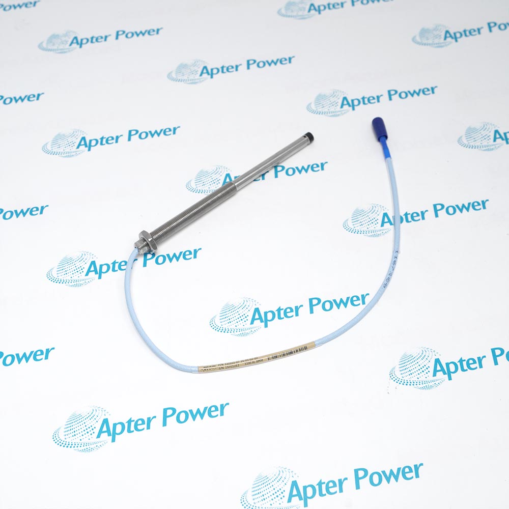
Product image is representative; revision or series may vary. Contact us to request a specific version.

Product Describe:

Bently Nevada 330500-04-01 is a solid-state piezo-velocity sensor for absolute bearing-housing, casing or structural vibration.
  • Manufacturer part number
    330500-04-01
  • Shipping
    Swift global dispatch
  • Condition
    New, original product
  • Shipping size (est.)
    7cm x 2.5cm x 2.5cm
  • Country of Origin
    USA
Get a quick price for 330500-04-01
E-mail *
Mobile
Company
Content *
Quantity *
Upload (gif, jpg, jpeg, png, bmp, doc, docx, xls, xlsx, ppt, pdf, csv)
For more information on how your data is processed and stored by Apterpower please read our privacy policy

What happens after you enquire

  • 0

    Review your reference

    Send the full marking, quantity and label photos. We review the item and any version details that need clarification.
  • 1

    Confirm the offer

    Check the quoted reference, condition, included items and expected dispatch date before approving your order.
  • 2

    Arrange dispatch

    Confirm delivery details and receive the tracking number when it becomes available.
  • Match the complete marking

    Include 330500-04-01 and every revision or approval marking visible on the item. Keep the exact reference on your enquiry and quotation.
  • Check the offered item before ordering

    Request available label and interface photos. Have your maintenance team compare the offered 330500-04-01 reference with the installed equipment and applicable Bently Nevada documentation.

Technical specifications for 330500-04-01

  • Manufacturer:
    Bently Nevada
  • Product Category:
    Machinery Monitoring Systems
  • Spare Part Number:
    330500-04-01
  • Weight:
    0.15 kg
  • Tariff Code:
    8537101190
  • Measurement:
    Absolute bearing-housing, casing or structural vibration
  • Sensitivity:
    3.94 mV/mm/s (100 mV/in/s) +/-5%
  • Frequency response:
    4.5 Hz to 5 kHz, +/-3 dB
  • Precision frequency band:
    6 Hz to 2.5 kHz, +/-0.9 dB
  • Velocity range:
    1270 mm/s (50 in/s) peak
  • Amplitude linearity:
    +/-2% to 152 mm/s (6 in/s) peak
  • Mounted resonant frequency:
    >12 kHz
  • Output bias voltage:
    -12 +/-3 V DC
  • Dynamic output impedance:
    <2400 ohm
  • Maximum signal cable length:
    305 m under stated cable conditions
  • Operating temperature:
    -55 to +121 deg C
  • Case material:
    316L stainless steel
  • Connector:
    2-pin MIL-C-5015, hermetically sealed
  • Mounting torque:
    32 to 46 kg cm maximum
  • Mounting adapter selection:
    1/4-20 UNC mounting adapter
  • Approval selection:
    CSA/US/C approval

Information

Overview Downloads Applications / Compatibility Product Precautions
  • Bently Nevada 330500-04-01 is a solid-state piezo-velocity sensor for absolute bearing-housing, casing or structural vibration.
Measurement role: Absolute vibration from a piezoelectric element with embedded velocity integration.
Selected mounting: 1/4-20 UNC mounting adapter; rigid surface preparation and torque govern high-frequency coupling.
Electrical output: 3.94 mV/mm/s sensitivity with -12 +/-3 V DC output bias.
330500-04-01 integrates a piezoelectric acceleration signal inside a solid-state 316L stainless-steel sensor to provide velocity-proportional output for absolute machine-housing vibration.

The selected 1/4-20 unc mounting adapter must be seated on a rigid prepared surface. Preserve connector polarity, cable support and the monitor current-limiting arrangement, and keep mounting torque within 32 to 46 kg cm.

Published sensitivity and frequency response assume the stated loading and mounting conditions. Final acceptance compares the installed velocity response with the established machine baseline across a controlled operating state.
Platform: 330500 Velomitor family. Verify the installed chain.
Technical downloads for Bently Nevada 330500-04-01: model-specific technical reference and installation review.
Use the exact order code and installed configuration when applying either document.
Prepare Bently Nevada 330500-04-01 using the approved machine documentation and site procedure.
Confirm the complete marking

Match every field of 330500-04-01 with the installed spare-parts and channel records.

Protect the sensing face

Prevent impact, metal-particle contact and contamination at the probe tip during handling.

Preserve the mechanical datum

Record thread engagement, reach, lock position, target relationship and as-found gap or bias before removal.

Control the cable route

Maintain the approved bend radius, connector protection and independent strain relief; do not twist the probe lead.

Restore the operating point

Use the approved stopped-machine procedure to restore the documented gap or bias.

Prove the matched channel

Verify as-left electrical indication and controlled machine response against the accepted baseline.

Alternative Names

Bently Nevada 330500-04-01 Bently Nevada 330500 04 01

Technical notes

Installation relationship: Use the 1/4-20 unc mounting adapter on a rigid bearing-housing or casing surface; flexible brackets can attenuate or distort response.

Electrical boundary: The embedded electronics require the documented current-limited monitor input, cable loading and polarity.

Technical reference: Bently Nevada 330500 Velomitor Piezo-velocity Sensor Datasheet, 141632 Rev. V.


FAQ View All FAQ

  • Where should 330500-04-01 be mounted?
    Use a rigid, prepared bearing-housing, casing or structural location that transfers the vibration of interest; avoid flexible covers, brackets and uneven surfaces.
  • How should the mounting interface of 330500-04-01 be prepared?
    Confirm the 1/4-20 unc mounting adapter, clean and flatten the surface, apply the approved installation method and keep torque within 32 to 46 kg cm.
  • What electrical checks apply to 330500-04-01?
    Confirm the current-limited input and polarity, record the unloaded bias, inspect the 2-pin connector and keep field cable loading within the documented design.
  • How should the response of 330500-04-01 be accepted?
    Compare the local velocity reading and monitor indication at a controlled operating state with the approved machine baseline.
  • What frequency range is documented for 330500-04-01?
    The manufacturer gives 4.5 Hz to 5 kHz at +/-3 dB and a 6 Hz to 2.5 kHz precision band at +/-0.9 dB under stated conditions.
  • What output bias is expected from 330500-04-01?
    Use the compatible current-limited input and compare the measured bias with the documented -12 +/-3 V DC boundary before interpreting vibration output.
  • When should 330500-04-01 be withheld from service?
    Do not release the channel if mounting stiffness, connector condition, bias, polarity or controlled response differs from the approved record.
  • What as-left record should accompany 330500-04-01?
    Retain the complete marking, mounting adapter, torque method, connector and cable condition, bias voltage, local velocity reading and monitor response.
SPEAK TO OUR TEAM
Let’s find the right solution for you.
Send us the part number, quantity and delivery destination. Our team will help confirm availability and lead time.
  • Whatsapp: +86 18030235313

    Send us a message.
  • sales13@apterpower.com

    Complete our online form.
  • +86 18030235313

    Speak to our team in your native language.