











Get Parts Quote
Name
Company *
Phone *
Email *
Address
City
State / Province / Region
Zipcode
Country
Quantity *
Part Number *
Manufacturer
Preferred Condition
Additional Information
Cancel
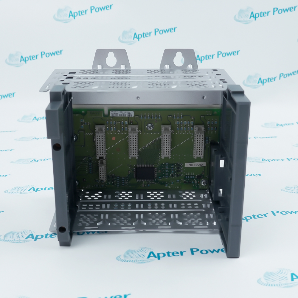
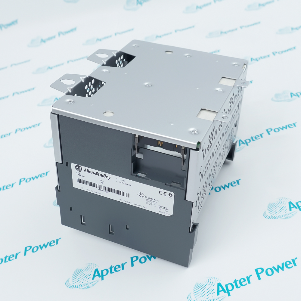
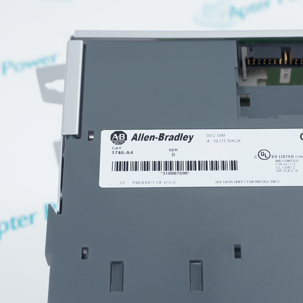
Allen-Bradley 1746-A4
Product image is representative; revision or series may vary. Contact us to request a specific version.

1746-A4

SLC 500 4-Slot Modular Chassis
In Stock
Ships by Monday, October 5
Fast Shipping Available

Product Describe:

Allen-Bradley 1746-A4 is a four-slot modular chassis for the SLC 500 controller family. It houses a compatible processor or I/O adapter and I/O modules, with a power supply mounted at the left side.

Ask our team:

Get a quick price for: 1746-A4
Quantity*
Upload (gif, jpg, jpeg, png, bmp, doc, docx, xls, xlsx, ppt, pdf, csv)
For more information on how your data is processed and stored by Apterpower please read our privacy policy.

Technical specifications for 1746-A4

Technical specifications for 1746-A4

  • Manufacturer:
    Allen-Bradley
  • Product Category:
    PLC Systems
  • Spare Part Number:
    1746-A4
  • Estimated shipping dimensions:
    17.8x14.5x17cm
  • Weight:
    0.7 kg
  • Tariff Code:
    8537101190
  • Counliy of origin:
    USA
  • System family:
    SLC 500
  • Chassis style:
    Modular
  • Module slots:
    4
  • Mounting type:
    Panel mount
  • Mounting tabs:
    4
  • Cooling method:
    Convection
  • Operating temperature:
    0 to 60 °C

Information

Information

Overview Manuals Common Applications Product Precautions
Allen-Bradley 1746-A4 provides the modular backplane and mechanical chassis for an SLC 500 controller or I/O-adapter assembly. It organizes the installed modules within an enclosure-mounted control system.
  • Supports a coordinated processor or I/O adapter and module assembly.
  • Provides the left-side mounting interface for an SLC power supply.
  • Permits cable-linked chassis expansion in an approved SLC 500 layout.
  • Allows unoccupied module positions to be protected with slot fillers.

Install 1746-A4 in a grounded control enclosure with the specified SLC 500 modules, power supply and interconnect hardware. Follow the cabinet drawing when locating the chassis and routing expansion cables.

Important Notice: Match the complete 1746-A4 chassis series to the installed system, then inspect the ground bond, mounting alignment, power-supply fit and module seating before energization.

Apter Power Allen-Bradley 1746-A4 Manuals and Guides
Apter Power Allen-Bradley 1746-A4 Product and System Technical Reference PDFRockwell Automation 1746-A4 SLC 500 Modular Chassis Installation Instructions (1746-IN016C-MU-P)

Important Notice: The first document is an Apter Power exact-model technical reference. The second is the unmodified Rockwell Automation installation publication for the SLC 500 modular chassis.


1746-A4 local SLC 500 controller chassisHouses the modular SLC processor and its approved I/O selection in an enclosure-mounted control rack.
1746-A4 I/O adapter chassisProvides a chassis position for a compatible I/O adapter and installed modules in a documented SLC 500 I/O layout.
1746-A4 linked chassis expansionForms one chassis in a cable-linked SLC 500 assembly when the system design needs additional module positions.
1746-A4 panel-mounted I/O assemblySupports a grounded cabinet installation with the specified power supply, module population and protective slot fillers.
Before installing Allen-Bradley 1746-A4, follow Rockwell Automation publication 1746-IN016C-MU-P and verify the cabinet arrangement against the actual chassis and connected hardware.
1
Match the complete 1746-A4 catalog and series marking to the approved SLC 500 cabinet design.
2
Remove chassis power before fitting or removing the processor, adapter, supply or I/O modules.
3
Keep drilling chips and other conductive debris away from installed electronics and the backplane.
4
Keep the mounting tabs flat; use suitable shims if the enclosure panel would distort the chassis.
5
Bond each chassis individually to the enclosure ground bus by the documented method.
6
Fit any specified chassis interconnect cable before attaching the power supply.
7
Protect unoccupied module openings with the documented 1746-N2 card-slot filler.
8
Record ground continuity, module seating and startup diagnostics before releasing the assembly.

Technical notes

Technical notes

Mount the 1746-A4 chassis flat against the enclosure back panel and bond it to the enclosure ground bus. Install an interconnect cable, if required, before attaching the chassis power supply.

FAQS

  • Which processor or adapter can be installed in Allen-Bradley 1746-A4?
    Use a processor or I/O adapter supported by the installed SLC 500 modular configuration; confirm its manual and power budget before fitting modules.
  • Where does the power supply mount on Allen-Bradley 1746-A4?
    The SLC 500 chassis power supply attaches at the left side. Select it for the total current demand of the installed processor and I/O modules.
  • Can Allen-Bradley 1746-A4 be part of a multiple-chassis system?
    Yes. The SLC 500 system selection guide permits up to three linked chassis when the appropriate chassis interconnect cable and system design are used.
  • How should Allen-Bradley 1746-A4 be grounded?
    Bond the chassis to the enclosure central ground bus using an individual equipment-grounding conductor, following publication 1746-IN016.
  • What should be checked before mounting Allen-Bradley 1746-A4?
    Check enclosure clearances, hole positions, mounting hardware and a flat back-panel contact. Do not distort the chassis when tightening the mounting tabs.
  • How are unused slots handled in Allen-Bradley 1746-A4?
    Use the 1746-N2 card slot filler for unused SLC 500 chassis openings to help keep debris out.
  • When should an interconnect cable be installed on Allen-Bradley 1746-A4?
    Install the specified chassis interconnect cable before attaching the power supply when the approved system layout uses more than one chassis.
  • What verifies Allen-Bradley 1746-A4 after installation?
    Check the complete catalog marking, ground bond, power-supply attachment, module seating and interconnect routing against the cabinet drawings before energizing.
Trusted by 5,000+ plants worldwide | Backed by our vast inventory of top-tier control parts, modules and cards, fast shipments are dispatched to cover your urgent needs. ABOUT US >>
Disclaimer: We are not an authorized distributor or distributor of the product manufacturer of this website, The product may have older date codes or be an older series than that available direct from the factory or authorized dealers. Because our company is not an authorized distributor of this product, the Original Manufacturer`s warranty does not apply.While many DCS PLC products will have firmware already installed, Our company makes no representation as to whether a DSC PLC product will or will not have firmware and, if it does have firmware, whether the firmware is the revision level that you need for your application. Our company also makes no representations as to your ability or right to download or otherwise obtain firmware for the product from our company, its distributors, or any other source. Our company also makes no representations as to your right to install any such firmware on the product. Our company will not obtain or supply firmware on your behalf. It is your obligation to comply with the terms of any End-User License Agreement or similar document related to obtaining or installing firmware.

We’re Here When You Need Us

From product insights to customer service needs, our experienced service team will focus on getting you what you need quickly

Enquire

Complete our online form.

Call Us

Speak to one of our team.

Live Chat

Send us a message.
