-
Match the complete marking
Include the complete 16710-45 marking and photographs of the installed connection and mounting position.
-
Check the offered item before ordering
Request available-unit label and connector photographs. Have your maintenance team compare the offered 16710-45 with the installed equipment and applicable Bently Nevada documentation.
Technical specifications for 16710-45
-
Manufacturer:Bently Nevada
-
Product Category:Machinery Monitoring Systems
-
Spare Part Number:16710-45
-
Weight:1.25 kg
-
Tariff Code:8537101190
-
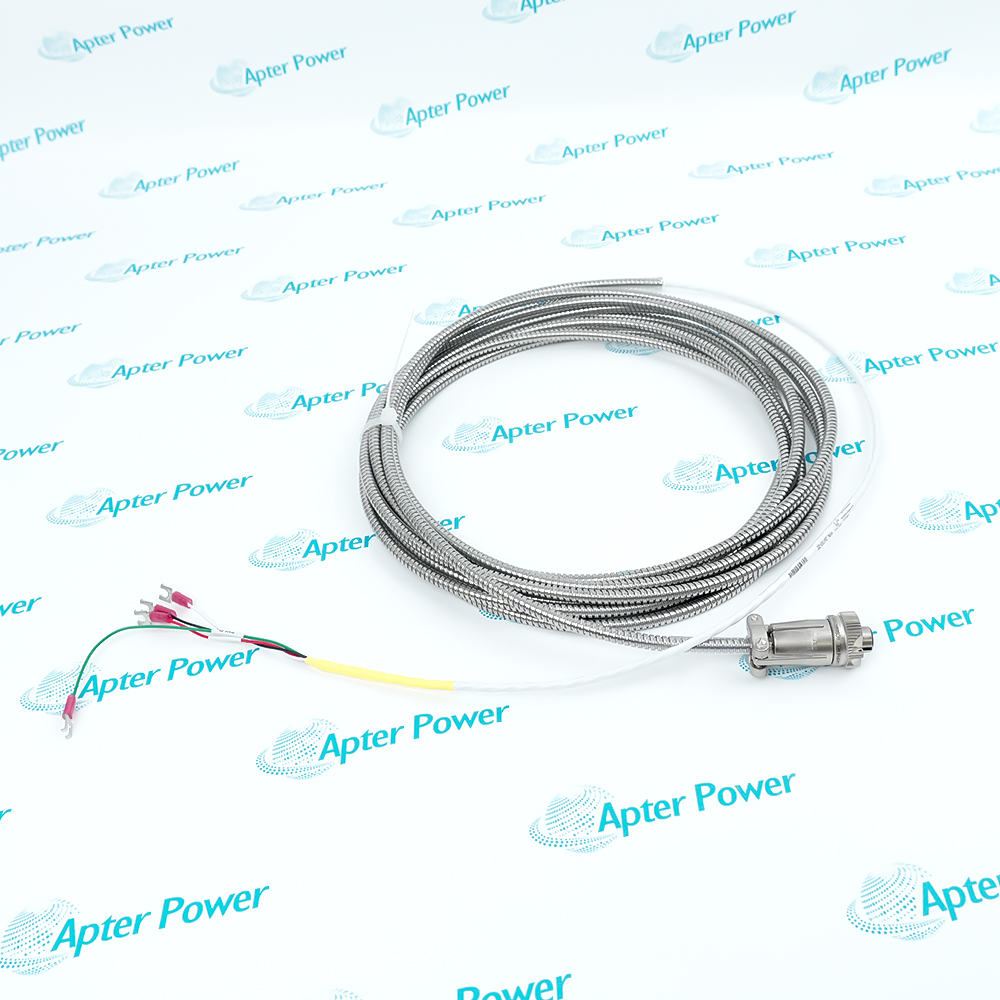
Cable family:16710 standard armored interconnect cable
-
Ordered length:45 ft (approximately 13.7 m)
-
Conductor arrangement:3 conductors plus shield
-
Conductor size:22 AWG (0.5 mm2)
-
Mechanical protection:Stainless-steel armor
-
Sensor-end connector:3-socket plug
-
Panel-end termination:Terminal lugs
-
Conductor identification:A white; B red; C black; shield green
-
Armor outside diameter:0.275 in (7 mm)
-
Cable section diameter:0.160 in (4.1 mm)
-
Prepared lead section:25.00 +/- 3.00 in (635 +/- 76 mm)
-
Ordering increment:1 ft (0.3 m)
-
Documented length range:3 to 99 ft (0.9 to 30 m)
Information
- The complete cable identity combines 22 AWG conductors, stainless-steel armor and a 45 ft order length for the documented acceleration-system connection.
Sensor-to-panel transition: A three-socket plug at one end and labeled terminal lugs at the other support a defined point-to-point connection.
Long installed reach: The 45 ft execution serves extended runs while retaining the documented cable construction.
The sensor end uses a three-socket connector with A, B and C contacts. The opposite end presents white, red and black conductors plus a green shield lead at terminal lugs, so conductor identity must be carried through the cabinet termination record.
The stainless-steel armor protects the route but does not replace correct support, bend control or shield practice. Acceptance includes point-to-point continuity, isolation and confirmation that the cable is landed on the intended receiver terminals.
16710-45 Official Datasheet Excerpt
Bently Nevada 330450 High Temperature Acceleration System Datasheet 169885 Rev. H. Selected original pages covering the applicable product family, technical data and ordering information.16710-45 Installation & Verification Guide
Apter Power field guide covering identity capture, installed relationships, controlled replacement, commissioning and handover.
Application scope: Use it as the documented armored connection between compatible Bently Nevada acceleration hardware and its receiving circuit.
Long machine-to-cabinet runs
Use the 45 ft execution where the routed path exceeds shorter standard lengths.Exposed cable routing
Apply the stainless-steel armor where the installed route requires additional mechanical protection.Defined three-contact interfaces
Preserve the A/B/C contact identity from the plug through the receiver termination.Maintenance replacement
Match length, connector orientation, conductor colors and lug destinations before removing the original cable.
Photograph the three-socket connector and every terminal lug before disconnection.
Support the assembly and use the connector body during removal and installation.
Restore the green shield lead exactly as shown on the approved drawing.
Retain A, B and C identification through the complete routed length.
Secure the armored run so vibration and weight do not load the connector.
Verify continuity, isolation and destination for each conductor and shield.
Alternative Names
Technical notes
Exact configuration: 45 ft armored 22 AWG three-conductor shielded cable with three-socket plug and terminal lugs
Connection boundary: Cable compatibility depends on the installed Bently Nevada acceleration-system connector and receiver drawing
Technical reference: Bently Nevada 330450 High Temperature Acceleration System Datasheet 169885 Rev. H

FAQ View All FAQ
-
How is the 45 ft length of 16710-45 interpreted?The suffix is ordered in one-foot increments; 45 selects a nominal 45 ft cable, approximately 13.7 m.
-
Which conductors are provided in 16710-45?The armored assembly contains three shielded 22 AWG conductors identified as A white, B red and C black, plus a green shield lead.
-
What termination arrangement does 16710-45 use?One end has a three-socket plug and the opposite end has terminal lugs for the three conductors and shield.
-
How should the shield of 16710-45 be reconnected?Follow the approved system drawing and reproduce the original green shield-lead destination; do not improvise a second ground point.
-
What should be checked before routing 16710-45?Confirm the complete path length, connector access, support points, armor clearance and the receiver terminal destination.
-
Can the stainless-steel armor on 16710-45 carry cable tension?No. Support the cable independently and avoid pulling, twisting or hanging the assembly by the armor or connector.
-
Which electrical checks are appropriate for 16710-45 before service?Verify A/B/C continuity, conductor-to-shield isolation, shield continuity and correct point-to-point landing with the system de-energized.
-
What evidence should be retained after installing 16710-45?Keep endpoint photographs, conductor and shield destinations, routed length, continuity results and the connected sensor and receiver identities.
Supporting new and legacy automation
-
Please try to be as accurate as possible with your search.
-
We can quote you on 1000s of specialist parts, even if they are not listed on our website.
-
We can't find any results for “”.
Related cases and sourcing guidance
View all case studiesYou May Also Like
Product Browsing History
-
Whatsapp: +86 18030235313
Send us a message. -
sales13@apterpower.com
Complete our online form. -
+86 18030235313
Speak to our team in your native language.