-
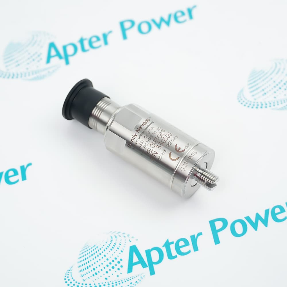
Match the complete marking
Include 330171-00-32-05-01-05 and every revision or approval marking visible on the item. Keep the exact reference on your enquiry and quotation.
-
Check the offered item before ordering
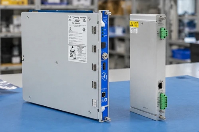
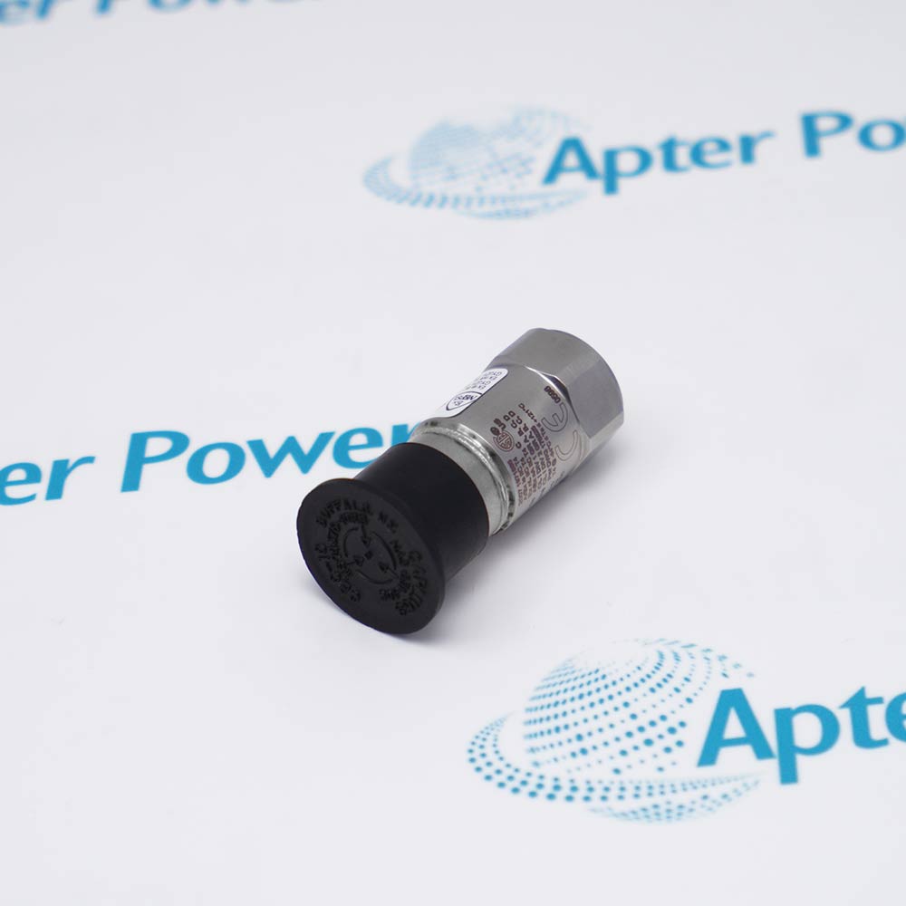
Request available label and connector photos. Have your maintenance team compare the offered 330171-00-32-05-01-05 reference with the installed equipment and applicable Bently Nevada documentation.
Technical specifications for 330171-00-32-05-01-05
-
Manufacturer:Bently Nevada
-
Product Category:Machinery Monitoring Systems
-
Spare Part Number:330171-00-32-05-01-05
-
Weight:0.04 kg
-
Tariff Code:8537101190
-
Product type:Unarmored 3300 5 mm proximity probe
-
Case thread:1/4-28 UNF-2A
-
Lead armor:No armor
-
Unthreaded length:0.0 in
-
Overall case length:3.2 in
-
Total probe length:0.5 m
-
Connector:Miniature coaxial ClickLoc with connector protector
-
Agency approval option:Multiple approvals
-
Probe tip diameter:5.2 mm
-
Cable impedance:75 ohm
-
Maximum cable outside diameter:2.8 mm, unarmored probe lead
-
Probe temperature range:-35 to +177 deg C
-
Maximum thread engagement:0.375 in for 1/4-28 mounting
-
Measurement principle:Eddy-current non-contact sensing
-
Electrical role:Passive probe in a matched transducer chain
Information
- The complete 330171-00-32-05-01-05 code fixes the probe mechanics, lead, connector and approval selection; the installed response still depends on the matching extension cable, Proximitor, target and monitor.
Connector protection: The ClickLoc protector controls moisture and contamination at the miniature coaxial interface.
Calibration ownership: Gap, scale and linearity are properties of the complete matched chain, not the probe alone.
The 0.5 m 75-ohm lead terminates in a miniature ClickLoc connector with protector. Preserve the electrical-length relationship to the installed Proximitor, keep the coaxial interface clean and dry, and do not let the connector carry cable weight.
The probe operates by eddy-current coupling to a conductive target. Final acceptance should restore the approved stopped-machine gap, compare bias and monitor indication with the maintenance baseline, and confirm operating response before protection is returned to service.
-
Bently Nevada 330171-00-32-05-01-05 technical reference
Apter Power reference with verified manufacturer data and exact-model applicability. -
Bently Nevada 330171-00-32-05-01-05 engineering guide
Apter Power installation, configuration, diagnostic and acceptance guidance.
Platform applications: The uses below depend on the installed controller configuration and approved system design.
-
Radial shaft vibration
Use a documented bearing location and matched transducer chain to observe shaft motion relative to the probe mounting. -
Axial position
Orient the probe toward an approved conductive thrust target and keep expected travel inside the characterized working region. -
Phase or speed reference
Use only where the installed target feature and monitoring channel are approved for once-per-turn reference measurement. -
Legacy-channel maintenance
Preserve the exact mechanical identity, cable construction, system length and companion electronics recorded for the installed channel.
Match every field of 330171-00-32-05-01-05 with the installed record before removal or installation.
Keep the tip, connector and cable free from impact, moisture, metal chips and unsupported loading.
Record reach, thread engagement, locknut position and target relationship before disturbing the installed component.
Maintain the approved bend radius, separation and strain relief; do not twist or crush the coaxial path.
Use the approved stopped-machine procedure and confirm expected target travel remains in the documented working region.
Verify the as-left electrical reading, monitor indication and operating response before return to service.
Alternative Names
Technical notes
Installation relationship: Use the 1/4-28 mounting, 3.2 in case and recorded locknut datum to establish the installed position.
System boundary: Treat gap, scale and linearity as complete-chain values, not standalone probe ratings.
Technical reference: Bently Nevada 3300 5 mm Transducer System Datasheet, 172036 Rev. R.

FAQ View All FAQ
-
How is the extension cable selected for 330171-00-32-05-01-05?The 0.5 m integral lead must be combined with the correct extension cable to equal the installed Proximitor system length. Confirm connector and approval identity as well as length.
-
How should the 3.2 in case of 330171-00-32-05-01-05 be checked in the mounting?Compare the 1/4-28 port depth, thread engagement, locknut location and target travel with the approved machine drawing before setting the gap.
-
What can cause gap-voltage drift after fitting 330171-00-32-05-01-05?Check mechanical locking, target thermal movement, connector contamination, cable insulation and Proximitor stability before changing monitor settings.
-
How should cross-talk be assessed around 330171-00-32-05-01-05?Verify probe spacing and target geometry, then observe adjacent channels during a controlled target movement. Correct physical spacing or routing before applying software compensation.
-
How should the complete marking of 330171-00-32-05-01-05 be recorded before removal?Photograph the full order identity, installed position, companion components and cable route. Save the stopped-machine baseline so the replacement can be returned to the same documented configuration.
-
Which companion-component check is required before installing 330171-00-32-05-01-05?Confirm the probe, extension cable and Proximitor or signal conditioner identities as a documented chain. Connector fit alone does not establish electrical calibration.
-
How should cable and connector integrity be tested for 330171-00-32-05-01-05?Isolate the channel, inspect contacts for moisture, contamination and damage, verify continuity and insulation with an approved method, and support the cable so the connector carries no tensile load.
-
What commissioning evidence should be retained for 330171-00-32-05-01-05?Retain complete markings, mechanical datum, companion identities, wiring or chain-length checks, as-left measurements and the operating response accepted by the maintenance authority.
Supporting new and legacy automation
-
Please try to be as accurate as possible with your search.
-
We can quote you on 1000s of specialist parts, even if they are not listed on our website.
-
We can't find any results for “”.
Related cases and sourcing guidance
View all case studiesYou May Also Like
Product Browsing History
-
330171-00-32-05-01-05Product Details -
86691-01250-0400-15Product Details -
9200-06-02-10-00Product Details -
9200-02-01-10-00Product Details -
76680-00-06-50-0-2Product Details -
9200-01-05-10-00Product Details -
991-06-70-01-00Product Details -
9324-RLD700NXENEProduct Details -
330930-040-04-CNProduct Details -
330980-50-CNProduct Details
-
Whatsapp: +86 18030235313
Send us a message. -
sales13@apterpower.com
Complete our online form. -
+86 18030235313
Speak to our team in your native language.