-
Match the complete marking
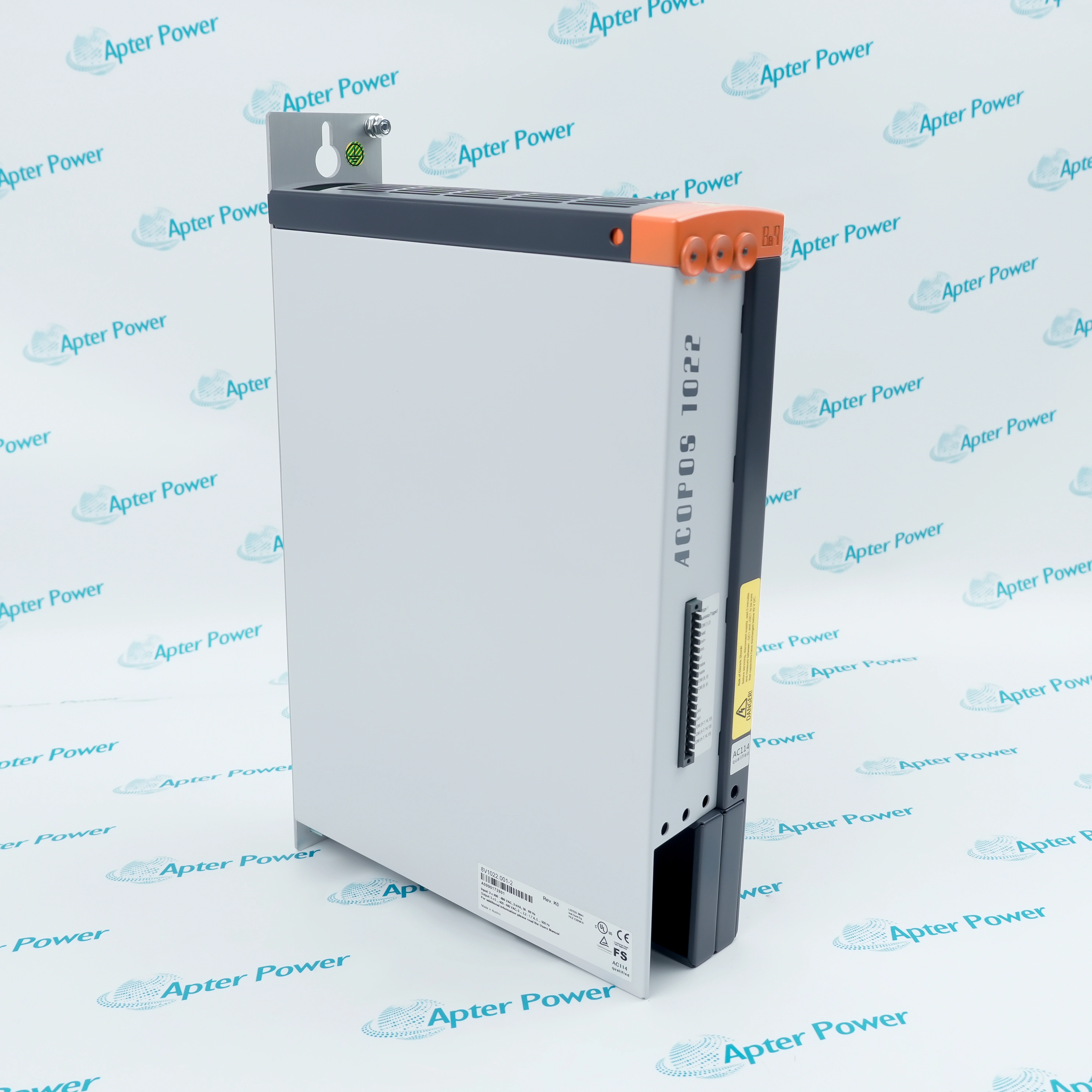
Provide the complete B&R 8BAC0133.000-1 marking. Verify 8BAC0133.000-1, slot 2 and the receiving pulse-interface arrangement.
-
Check the offered item before ordering
Request available label and connector photos. Have your maintenance team compare the offered 8BAC0133.000-1 with the installed equipment and applicable B&R instructions.
Technical specifications for 8BAC0133.000-1
-
Manufacturer:B&R
-
Product Category:General Automation
-
Spare Part Number:8BAC0133.000-1
-
Weight:0.2 kg
-
Tariff Code:8537101190
-
Host slot:ACOPOSmulti slot 2
-
Signal outputs:3 differential RS422 channels: A, B, reference
-
Maximum frequency:1 MHz
-
Maximum cable length:75 m
-
Receiver termination:120 Ω
-
Cable impedance:120 Ω, shielded
-
Switching delay:≤50 ns, both transitions
-
Power consumption:2 W maximum
-
Connector:Coded 9-pin female D-sub
-
Startup output state:High impedance until software initialization
-
Output-to-host isolation:Yes
-
Output-to-output isolation:No
Information
- B&R 8BAC0133.000-1 supplies an encoder-style pulse interface to a receiving device while obtaining its power internally from the ACOPOSmulti host.
Frequency: Up to 1 MHz
Connection: Coded D-sub with receiver termination
The coded nine-pin female D-sub connection assigns A to pin 2, inverted A to 3, B to 4, inverted B to 9, reference to 8 and inverted reference to 7. Pin 6 carries the shared signal-ground reference.
Maximum switching frequency is 1 MHz and the specified cable length is up to 75 m. The receiver requires 120-ohm termination and a shielded cable with 120-ohm characteristic impedance; the shield is connected at both ends. Outputs remain high impedance until software initialization.
8BAC0133.000-1 Official Technical Excerpt
B&R 8BAC0133.000-1: original manufacturer technical information covering the specified interfaces and operating limits. PDF · 3 pages.8BAC0133.000-1 Installation & Verification Guide
Apter Power installation and verification guide covering identify the emulation role, map the differential pairs, apply receiver termination, observe software initialization, check the reference pulse. PDF · 5 pages.
Application scope: The applications below describe its technical role. Select associated hardware and configuration for the actual installation.
Encoder-style pulse output
Provide A/B/reference emulation to a compatible differential receiver.Drive-position distribution
Transfer the configured emulation signal from an ACOPOSmulti host to external equipment.Isolated host interface
Use the output-to-host isolation while establishing the required remote signal reference.Pulse-channel verification
Check pair polarity, reference pulse and receiver termination during commissioning.
Verify the ACOPOSmulti host and the specified slot position before fitting the option. Follow the host isolation and stored-energy procedure for hardware work.
Include the pin-6 common reference in the same cable as the signal conductors. Use the intended receiver-side ground reference for the isolated output circuit.
Apply the cable shield at both ends and inspect the connector shield continuity. Keep the installation within the 75 m maximum cable length.
Use suitable differential instrumentation or receiver diagnostics to check pulse frequency and direction interpretation. Keep the test within the 1 MHz maximum frequency.
Save pair wiring, termination, reference connection, configured emulation behavior and test results. Confirm the receiving equipment responds correctly before enabling dependent motion.
Verify the reference pair at pins 8 and 7 and its interpretation by the receiving device. A working A/B count does not by itself prove reference-pulse alignment.
Alternative Names
Technical notes
Operating boundary: The 250 mA peak short-circuit figure is a protection characteristic, not a normal load-current rating. Receiver compatibility must follow the RS422 interface requirements.
Integration details: Preserve slot 2, differential pair assignments, receiver termination, shielding and signal reference when replacing the emulation option.
Technical basis: B&R ACOPOSmulti User's Manual, V1.30. 8BAC0133.000-1 is a slot-2 ABR encoder-emulation output option. Output isolation, receiver termination and the complete drive operating limits must be respected.

FAQ View All FAQ
-
Does 8BAC0133.000-1 read an external encoder or emulate one?It produces A/B/reference encoder-emulation outputs. It is not an encoder-input module.
-
Which ACOPOSmulti slot accepts 8BAC0133.000-1?The option is specified for slot 2. Confirm the compatible host and slot configuration before installation.
-
Why is a ground-reference conductor needed with 8BAC0133.000-1?The outputs are isolated from the host and need a reference to the receiving device. Include that reference in the same cable as the signals.
-
Where should the 120-ohm termination for 8BAC0133.000-1 be installed?At the remote receiving station, using the specified 120-ohm characteristic-impedance shielded cable.
-
What electrical separation exists between the host and the A/B/reference signals on 8BAC0133.000-1?No. They are isolated from the ACOPOSmulti host but share the output-side reference.
-
What output state should be expected from 8BAC0133.000-1 before software initialization?The outputs remain high impedance until software initialization, so an absent pulse train at that stage is not automatically a wiring fault.
-
Which pins carry the reference pulse on 8BAC0133.000-1?Pin 8 is the reference signal and pin 7 is its inverted counterpart; pin 6 provides the common signal reference.
-
How should the shield of the cable connected to 8BAC0133.000-1 be handled?Use a shielded cable and apply the shield at both ends, following the specified receiver and grounding arrangement.
Supporting new and legacy automation
-
Please try to be as accurate as possible with your search.
-
We can quote you on 1000s of specialist parts, even if they are not listed on our website.
-
We can't find any results for “”.
Related cases and sourcing guidance
View all case studiesYou May Also Like
Product Browsing History
-
Whatsapp: +86 18030235313
Send us a message. -
sales13@apterpower.com
Complete our online form. -
+86 18030235313
Speak to our team in your native language.