Speak to a sourcing specialist
sales13@apterpower.com

1747-L30C

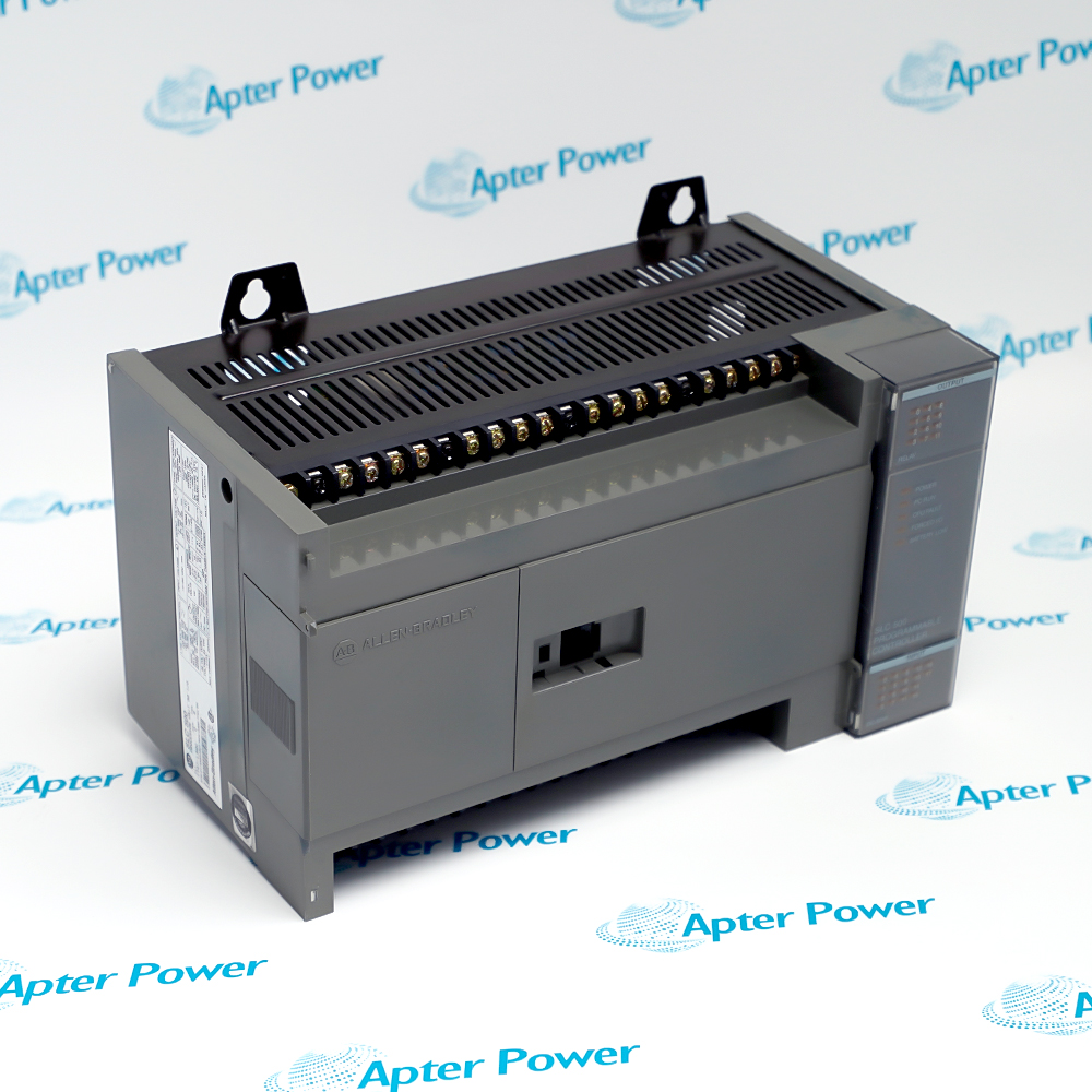
Fixed-I/O Programmable Logic Controller
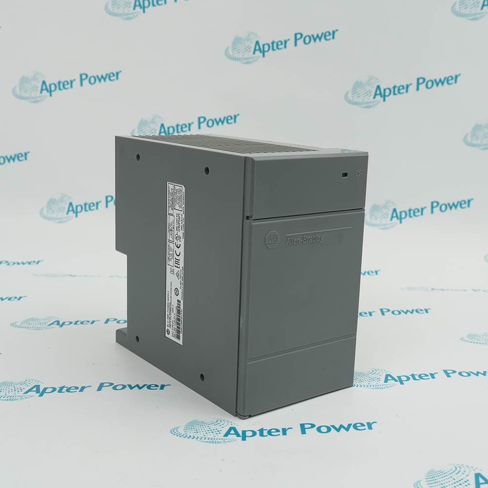
Allen-Bradley 1747-L30C
Product image is representative; revision or series may vary. Contact us to request a specific version.

Product Describe:

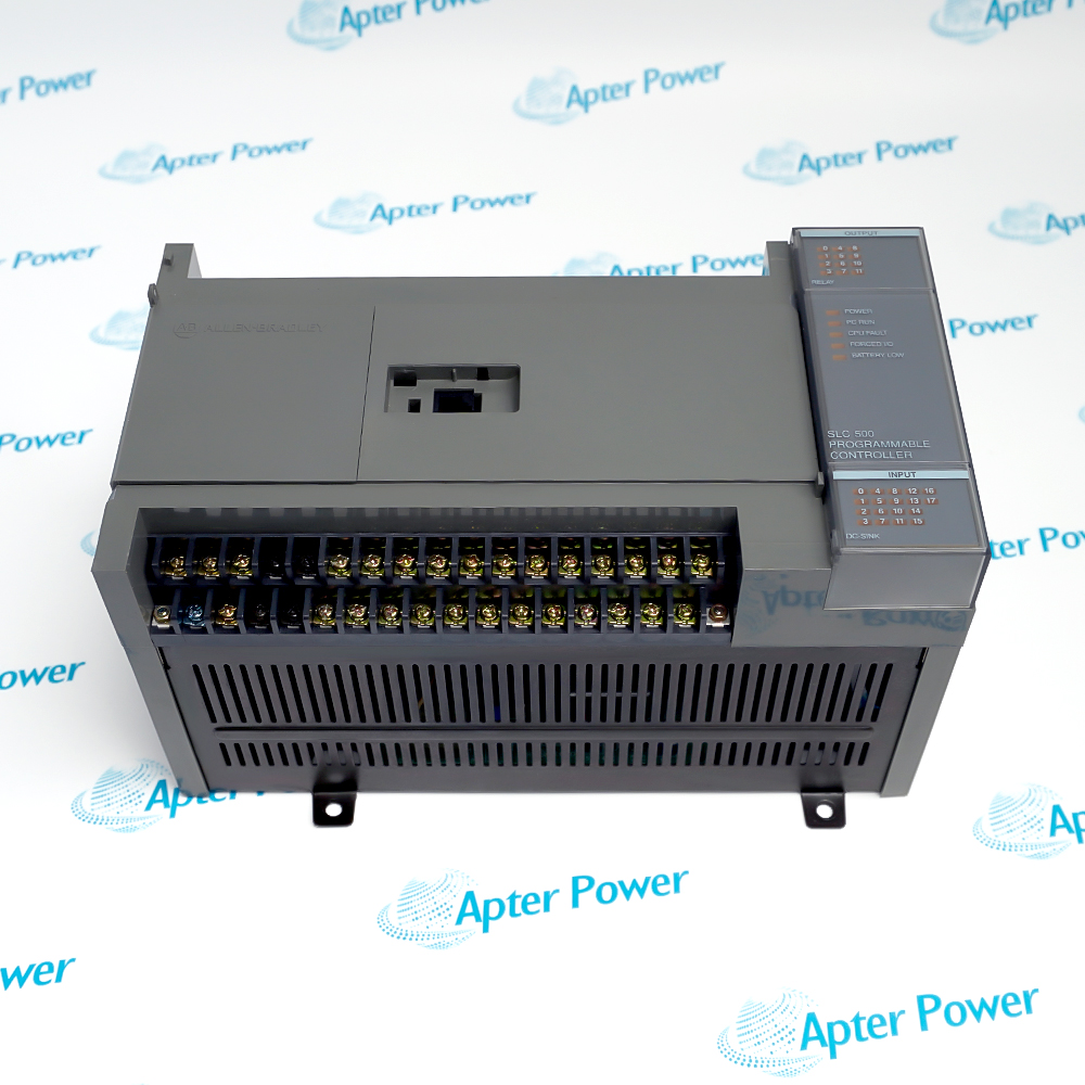
Allen-Bradley 1747-L30C combines a fixed controller with eighteen DC sinking inputs and twelve relay outputs, powered from an AC supply.
  • Manufacturer part number
    1747-L30C
  • Shipping
    Swift global dispatch
  • Condition
    New, original product
  • Shipping size (est.)
    3.5x13x14.5cm
  • Country of Origin
    USA
Get a quick price for 1747-L30C
E-mail *
Mobile
Company
Content *
Quantity *
Upload (gif, jpg, jpeg, png, bmp, doc, docx, xls, xlsx, ppt, pdf, csv)
For more information on how your data is processed and stored by Apterpower please read our privacy policy

What happens after you enquire

  • 0

    Review your reference

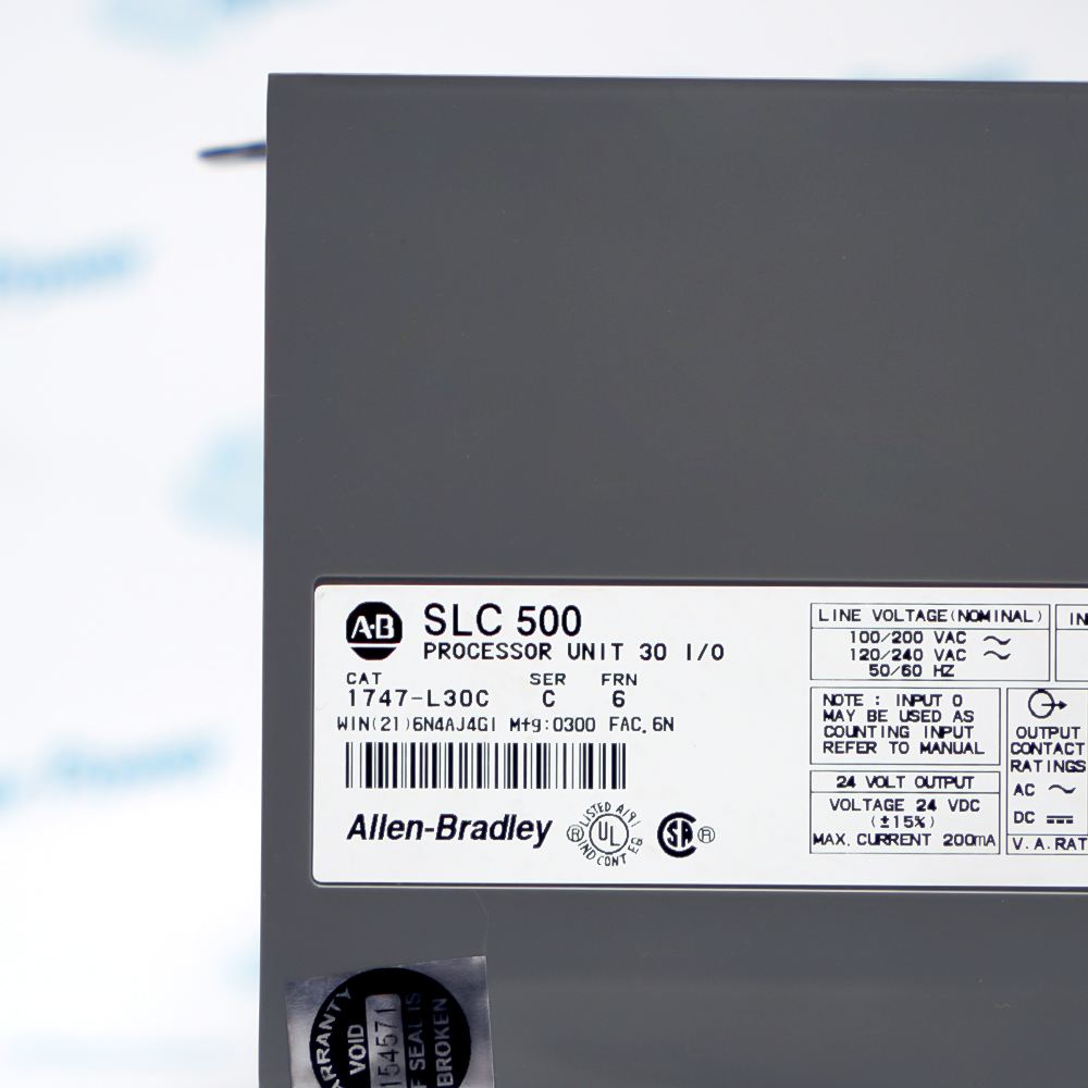
    Send the complete 1747-L30C reference, label photographs and required quantity. Check the L30C marking, AC-power/DC-sinking-input execution, relay terminal groups and installed memory accessories.

  • 1

    Confirm the offer

    Review the offered 1747-L30C configuration, condition and included items. Confirm the controller, terminal covers, memory module, backup battery if supplied, programming accessories and any expansion chassis in the quotation.

  • 2

    Arrange dispatch

    Confirm quantity, dispatch date and delivery details for 1747-L30C in the quotation.

  • Match the complete marking

    Match the complete Allen-Bradley 1747-L30C marking and the actual installed hardware configuration before approving the order. Check the L30C marking, AC-power/DC-sinking-input execution, relay terminal groups and installed memory accessories.

  • Check the offered item before ordering

    Request clear photographs of the offered 1747-L30C and ask your maintenance team to compare its markings and interfaces with the installed equipment and applicable Allen-Bradley instructions.

Technical specifications for 1747-L30C

  • Manufacturer:
    Allen-Bradley
  • Product Category:
    PLC Systems
  • Spare Part Number:
    1747-L30C
  • Weight:
    0.25 kg
  • Tariff Code:
    8537101190
  • Digital inputs:
    18 DC sinking
  • Input operating voltage:
    10-30 V DC
  • Relay outputs:
    12
  • AC supply range:
    85-265 V AC
  • Sensor power:
    24 V DC, 200 mA
  • High-speed input:
    Input 0
  • Program capacity:
    1K instructions
  • Relay maximum continuous current:
    2.5 A per output; 8 A per group
  • Relay voltage range:
    5-265 V AC or 5-125 V DC
  • Operating temperature:
    0-60 degrees C

Information

Overview Downloads Applications / Compatibility Product Precautions
  • Allen-Bradley 1747-L30C coordinates a compact machine sequence with separate field-output supply groups, making output common wiring and restart behavior central to replacement work.
Controller architecture: Integrated fixed I/O
Field outputs: Separately supplied relay groups
Service focus: Program retention, output mapping and controlled restart
DC sinking inputs are intended for compatible sourcing field devices. Input 0 has a high-speed-counter function and different current and off-state characteristics from the other inputs, so its wiring and use deserve a separate review.

The relay output commons divide the twelve outputs into isolated groups. Different field voltages may be assigned to the appropriate groups, but the group and individual contact limits still apply; the AC controller supply does not automatically supply the relay loads.

Program memory is capacitor-backed RAM with optional battery support and optional nonvolatile memory devices. Capture the installed application and backup arrangement before replacement, then verify scan-dependent behavior, forced I/O and restart interlocks in the complete machine sequence.
Controller platform reference: SLC 500 fixed controller. Follow the applicable installation instructions and approved design.
Technical and service documents for Allen-Bradley 1747-L30C, covering the applicable hardware arrangement and its engineering verification.
Original manufacturer pages retain their technical context. Use the Apter Power guide with the applicable manufacturer instructions and approved installation design.
System and supply context: Allen-Bradley 1747-L30C serves the SLC 500 fixed controller configuration. The examples below apply to the complete installed signal or control path.

Application scope: Select compatible companion hardware and retain the intended measurement or control function. Accessories are included only when itemized in the offered assembly.
Prepare Allen-Bradley 1747-L30C for its configured installation using these checks.
Program and memory capture

Save the application, I/O assignments, forces and communication settings. Identify the installed RAM-backup and nonvolatile-memory arrangement before isolation.

Supply-group separation

Trace the controller AC supply and all four relay field-supply groups. Label each common and retain the intended protective devices.

Input-0 assessment

Check the sourcing sensor connected to the sinking inputs and review input 0 separately for its high-speed function and current demand.

Relay-duty verification

Test the intended output paths with suitable controlled loads. Confirm contact duty and suppression for the actual field devices.

Controlled machine restart

Restore the verified program and inspect forcing before allowing outputs. Test startup interlocks and the required operating sequence under the site procedure.

Complete configuration retention

Retain the final 1747-L30C identity, wiring and verified configuration with the machine maintenance record.

Alternative Names

Allen-Bradley 1747-L30C

Technical notes

Output group separation: Follow the four relay supply groups shown for this exact controller. Preserve the field commons and protective devices; do not bridge groups merely because they share a controller housing.

Counter input distinction: Input 0 has different current demand and off-state limits from ordinary DC inputs. Check sensor drive capability and the high-speed application before transferring a signal to or from that terminal.

Contact duty: Continuous-current limits do not replace make/break ratings. Inductive loads and switching frequency require a contact-duty and suppression review in addition to the steady-state load calculation.


FAQ View All FAQ

  • Why can 1747-L30C be powered while none of its field loads operate?
    Relay contacts require their field-side supply through the assigned output commons. Controller power alone does not energize the external load circuits.
  • Can the relay commons on 1747-L30C be bridged during rewiring?
    Only if the approved circuit design permits it. The outputs are arranged in isolated supply groups, and bridging can defeat separation between circuits or different voltages.
  • Why is input 0 on 1747-L30C not identical to the other DC inputs?
    It supports the high-speed counter and has different input current and off-state characteristics. Verify the source capability and intended counter function before using it as an ordinary terminal.
  • What should be preserved before removing 1747-L30C from a machine?
    Back up the application and record I/O mapping, forces, communication settings and memory-backup arrangement. A replacement controller without that application context cannot reproduce the machine sequence reliably.
  • Does the maximum continuous relay current on 1747-L30C cover every inductive load?
    No. Make/break ratings and switching transients also apply. Check the actual load duty and suitable suppression instead of using only the steady-state current.
  • How can sensor loading affect the auxiliary supply on 1747-L30C?
    The total sensor demand must remain within the available user-power capacity, including the input-0 requirement where applicable. A supply that collapses under load can create multiple input faults.
  • Why should a restart test on 1747-L30C include output forces and interlocks?
    A restored program can still contain forcing or a different starting state. Confirm that controlled power restoration cannot bypass the intended sequence or energize an unintended output.
  • Can a scan-time estimate alone validate a counting application on 1747-L30C?
    No. Confirm whether the signal uses the high-speed path or ordinary scanned input logic, then assess pulse width, input response and program behavior together.
SPEAK TO OUR TEAM
Let’s find the right solution for you.
Send us the part number, quantity and delivery destination. Our team will help confirm availability and lead time.
  • Whatsapp: +86 18030235313

    Send us a message.
  • sales13@apterpower.com

    Complete our online form.
  • +86 18030235313

    Speak to our team in your native language.