-
Match the complete marking
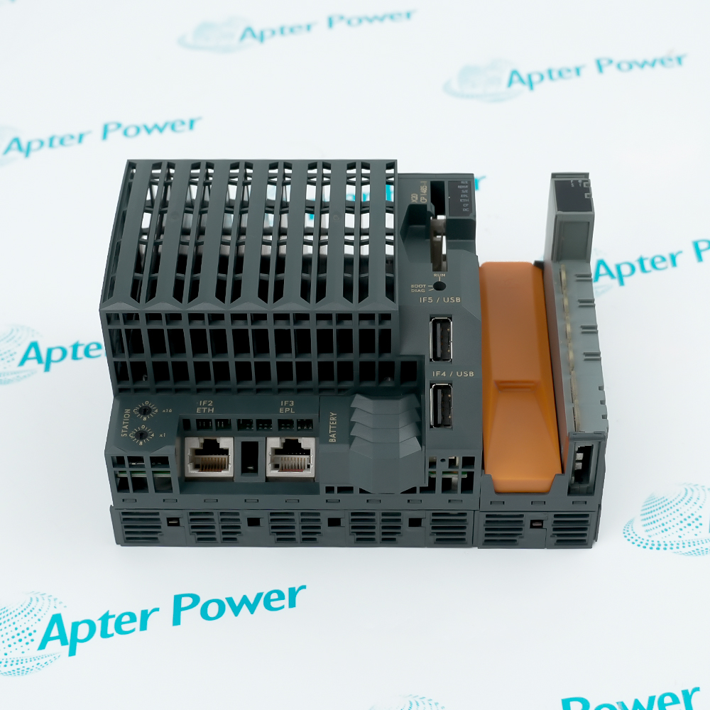
Match the complete B&R X20IF1086-2 marking, hardware revision and selected configuration to the installed position. Check physical layer and network rate against the installed configuration.
-
Check the offered item before ordering
Request label and connection photographs. Have your maintenance team compare the offered X20IF1086-2 with the installed equipment and applicable B&R instructions.
Technical specifications for X20IF1086-2
-
Manufacturer:B&R
-
Product Category:PLC Systems
-
Spare Part Number:X20IF1086-2
-
Weight:0.65 kg
-
Tariff Code:8537101190
-
Physical layer:100BASE-FX
-
Network rate:100 Mbit/s
-
Optical port:1 duplex LC
-
Fiber type:Multimode 62.5/125 or 50/125 micrometres
-
Typical wavelength:1300 nm
-
POWERLINK segment:Up to 2 km
-
Ethernet TCP/IP segment:Up to 400 m
-
Optical budget:11 dB (62.5/125); 7.5 dB (50/125)
-
Power consumption:1.8 W; revisions before D0: 2 W
-
Horizontal operation:-25 to +60 C
-
Vertical operation:-25 to +50 C
Information
- B&R X20IF1086-2 extends the controller network over multimode fiber, allowing the same interface hardware to operate as a managing or controlled node.
Network rate: 100 Mbit/s
Optical port: 1 duplex LC
The permitted span depends on operating mode: POWERLINK allows up to 2 km between stations, while Ethernet TCP/IP is limited to 400 m. Optical budget also depends on the fiber, at 11 dB for 62.5/125 micrometre and 7.5 dB for 50/125 micrometre cable.
POWERLINK operation is half-duplex; full-duplex is available in Ethernet mode only. The project firmware and station settings must match the network role, and successful optical link establishment must be followed by cyclic communication verification.
X20IF1086-2 Official Technical Excerpt
Original B&R technical material applicable to X20IF1086-2, covering function, interfaces and operating limits. PDF · 8 pages.X20IF1086-2 Installation & Verification Guide
Apter Power field guide for the selected connection, configuration and functional tests. PDF · 5 pages.
Application scope: The technical values apply to this model in the specified installation and configuration. The examples below address the stated product function.
Optical controller expansion
Add a fiber-based network interface to a compatible X20 controller slot.Long POWERLINK segments
Use an optical span within 2 km when the fiber budget and POWERLINK topology permit it.Electrical separation
Use the isolated optical network boundary where a conductive network path is unsuitable.Network-role configuration
Implement the managing or controlled node role assigned in the Automation Studio project.
Record whether the installed interface is the managing node or a controlled node before removing it.
Compare the Automation Studio hardware entry and firmware upgrade with the controller project.
Identify both fiber cores and connector ends.
Calculate the installed fiber and connector losses against the applicable 11 dB or 7.5 dB budget.
Isolate the controller according to its service procedure before changing the interface.
Restore the station-number selection and network role before returning communication to service.
Alternative Names
Technical notes
Project firmware level: Compare the Automation Studio hardware entry and firmware upgrade with the controller project. The replacement receives its project firmware automatically, so keep the machine in its maintenance state during initialization.
Keep the optical ends clean: Isolate the controller according to its service procedure before changing the interface. Inspect the LC connector seating and restore the labeled optical pair without stressing the fiber bend or pulling directly on the cable.
Check loss-of-network response: Use the approved network test to confirm the controller reaction when the optical path or managing node is lost. Restore the connection and ensure recovery is consistent with the configured network behavior before releasing the machine.

FAQ View All FAQ
-
Can X20IF1086-2 use an ordinary RJ45 Ethernet cable?No. Its port is duplex LC for multimode optical fiber, not a copper Ethernet socket.
-
Why does X20IF1086-2 have different Ethernet and POWERLINK distance limits?The allowed segment is mode-dependent: 400 m for Ethernet TCP/IP and 2 km for POWERLINK. The selected mode and optical power budget must both be satisfied.
-
Which fiber offers the larger optical budget on X20IF1086-2?The 62.5/125 micrometre fiber option has an 11 dB budget, compared with 7.5 dB for 50/125 micrometre fiber.
-
Does X20IF1086-2 negotiate its Ethernet speed automatically?No. Autonegotiation is not supported; the interface operates at 100 Mbit/s.
-
When is full-duplex operation available on X20IF1086-2?Full-duplex is available in Ethernet mode. POWERLINK mode does not support full-duplex operation.
-
What does an illuminated L/A X1 indicator on X20IF1086-2 establish?A steady light establishes a link to the remote station. Blinking indicates link plus Ethernet activity; neither alone proves the application data are correct.
-
How does firmware reach X20IF1086-2 after replacement?Firmware belongs to the Automation Studio project, and the module is automatically brought to that project level. Updating the available firmware requires the appropriate hardware upgrade.
-
Why should the hardware revision of X20IF1086-2 be included in the power calculation?Power consumption is 1.8 W from revision D0, while earlier revisions require 2 W. The controller expansion budget must allow the actual revision.
Supporting new and legacy automation
-
Please try to be as accurate as possible with your search.
-
We can quote you on 1000s of specialist parts, even if they are not listed on our website.
-
We can't find any results for “”.
Related cases and sourcing guidance
View all case studiesYou May Also Like
Product Browsing History
-
Whatsapp: +86 18030235313
Send us a message. -
sales13@apterpower.com
Complete our online form. -
+86 18030235313
Speak to our team in your native language.