-
Match the complete marking
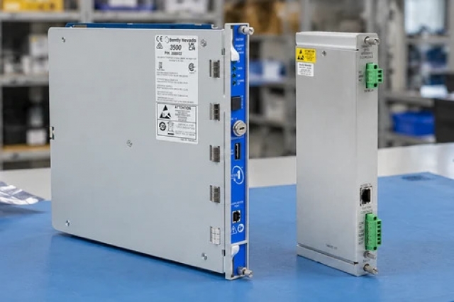
Match the complete B&R X20SL8010 marking, hardware revision and selected configuration to the installed position. Check supported safety nodes and shortest task-class cycle against the installed configuration.
-
Check the offered item before ordering
Request label and connection photographs. Have your maintenance team compare the offered X20SL8010 with the installed equipment and applicable B&R instructions.
Technical specifications for X20SL8010
-
Manufacturer:B&R
-
Product Category:PLC Systems
-
Spare Part Number:X20SL8010
-
Weight:0.06 kg
-
Tariff Code:8537101190
-
Supported safety nodes:20 maximum
-
Shortest task-class cycle:1 ms
-
POWERLINK transfer rate:100 Mbit/s
-
Network ports:2 shielded RJ45; internal hub
-
Maximum segment length:100 m between stations
-
Nominal supply:24 V DC -15%/+20%
-
Power consumption:5.1 W
-
Functional safety capability:SIL 3; Category 4 / PL e
-
Mission time:20 years maximum
-
Proof-test interval:20 years
-
Horizontal operating temperature:0 to 55°C
-
Vertical operating temperature:0 to 45°C
Information
- B&R X20SL8010 coordinates a safety application by supervising its configuration, assigning retained parameters to replacement modules and executing the safety program.
Shortest task-class cycle: 1 ms
POWERLINK transfer rate: 100 Mbit/s
The supported engineering environment includes Automation Studio 3.0.80 or later, Automation Runtime 3.00 or later, SafeDESIGNER 2.71 through 3.0 and Safety Release 1.3 through 1.6. These compatibility limits must be considered as a combination rather than independently selecting the newest tool version.
SafeMOTION is supported, while machine options are not. Inter-controller communication is limited to SafeLOGIC SL8001 or SL8011 partners. SafeKEY application memory is ordered separately; the controller rating alone does not establish the achieved safety integrity of the complete machine.
X20SL8010 Technical Reference
Apter Power technical reference organizing the X20SL8010 manufacturer specifications by controller function and interface. PDF · 5 pages.X20SL8010 Installation & Verification Guide
Apter Power field guide for the selected connection, configuration and functional tests. PDF · 5 pages.
Application scope: Controller capabilities require validation within the complete safety application. The examples below address the stated product function.
Central safety logic
Execute the approved safety program and supervise its associated safety-node configuration.Replacement parameter management
Assign retained application parameters to replacement safety modules within the validated configuration.SafeMOTION integration
Coordinate supported SafeMOTION functions with the controller's safety application.Distributed safety network
Connect up to 20 supported safety nodes through the configured POWERLINK architecture.
Retain the approved project and configuration before removing the controller.
Record the compatible SafeKEY and its application identity.
Compare Automation Studio, Automation Runtime, SafeDESIGNER and Safety Release versions as a set.
Check any SafeLOGIC inter-controller communication in the project.
Mark both shielded RJ45 connections and their station destinations.
Verify the 24 V DC supply within its -15% to +20% tolerance and allow for 5.1 W consumption.
Alternative Names
Technical notes
Preserve the SafeKEY assignment: Record the compatible SafeKEY and its application identity. Application memory is a separate component, so confirm that the offered controller and retained memory together support the intended replacement procedure before disconnecting the original assembly.
Rebuild the POWERLINK topology: Mark both shielded RJ45 connections and their station destinations. Keep each segment within 100 m and restore the intended topology; a link indicator does not confirm that the safety nodes are assigned to the correct application.
Retain validation and service evidence: Record the restored application identity, node assignments, tool versions and safety-function test results. Preserve the mission-time and proof-test planning for the complete safety application rather than treating a successful boot as final acceptance.

FAQ View All FAQ
-
How many safety nodes can X20SL8010 supervise?It supports up to 20 safety nodes. The complete application must also meet its configured timing and resource requirements.
-
Which SafeLOGIC controllers can communicate with X20SL8010?The supported inter-controller partners are SL8001 and SL8011.
-
Does X20SL8010 support the machine-options function?No. Machine options are not supported, although SafeMOTION is supported.
-
What is the shortest task-class cycle available on X20SL8010?The shortest task-class cycle is 1 ms. Overall safety response also includes communication, I/O and actuator timing.
-
Is SafeKEY application memory included with X20SL8010?SafeKEY application memory is ordered separately. Preserve the compatible memory and approved application when replacing the controller.
-
Which SafeDESIGNER range is listed for X20SL8010?SafeDESIGNER 2.71 through 3.0 is supported, together with the compatible Safety Release range 1.3 through 1.6.
-
Does the SIL 3 capability of X20SL8010 certify the whole machine?No. The controller has SIL 3 and Category 4 / PL e capability, but the achieved machine safety function depends on the complete architecture, configuration and validation.
-
What POWERLINK segment length is permitted with X20SL8010?The maximum cable length between two stations is 100 m at the 100 Mbit/s transfer rate.
Supporting new and legacy automation
-
Please try to be as accurate as possible with your search.
-
We can quote you on 1000s of specialist parts, even if they are not listed on our website.
-
We can't find any results for “”.
Related cases and sourcing guidance
View all case studiesYou May Also Like
Product Browsing History
-
Whatsapp: +86 18030235313
Send us a message. -
sales13@apterpower.com
Complete our online form. -
+86 18030235313
Speak to our team in your native language.