Speak to a sourcing specialist
sales13@apterpower.com

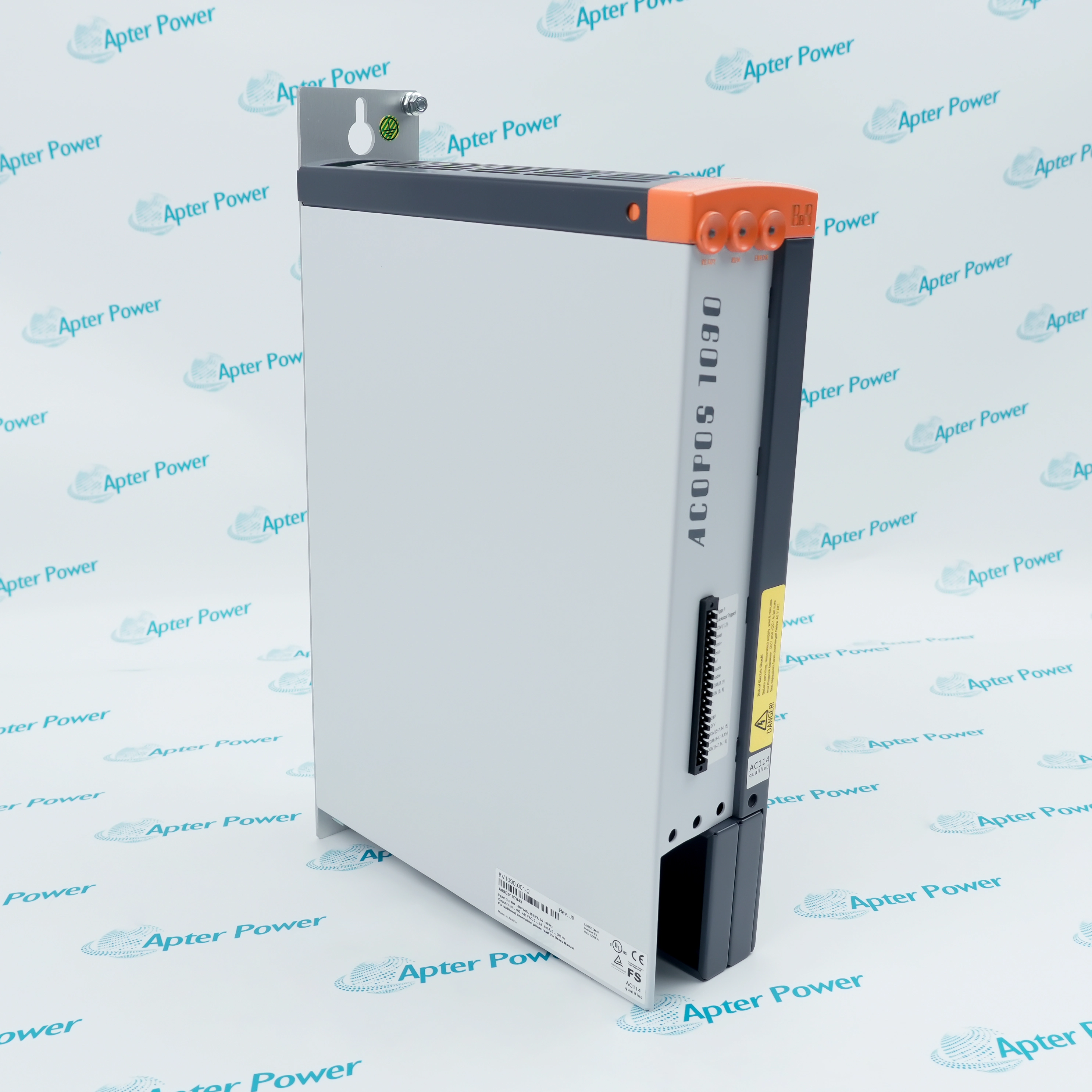
8V1022.00-2

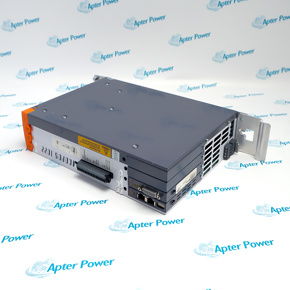
ACOPOS Servo Drive
B&R 8V1022.00-2 (1)
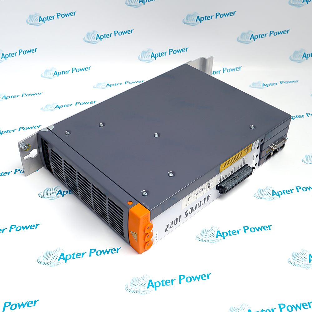
B&R 8V1022.00-2 (2)
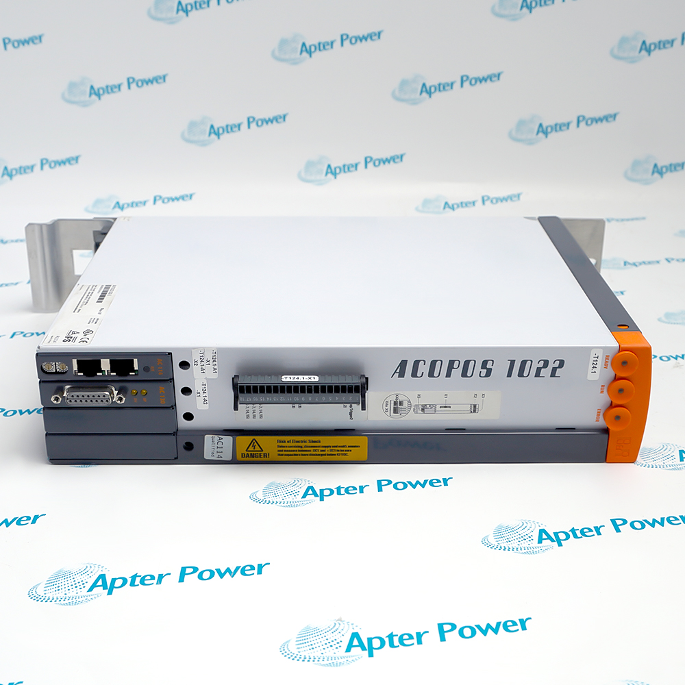
B&R 8V1022.00-2 (3)
B&R 8V1022.00-2 (1)
B&R 8V1022.00-2 (2)
B&R 8V1022.00-2 (3)
Product image is representative; revision or series may vary. Contact us to request a specific version.

Product Describe:

B&R 8V1022.00-2 is identified as a acopos servo drive for the B&R ACOPOS motion-control platform. The complete marking and installed interface arrangement must be matched before replacement.
  • Manufacturer part number
    8V1022.00-2
  • Shipping
    Swift global dispatch
  • Condition
    New, original product
  • Shipping size (est.)
    7.2cm × 3.5cm × 37.5cm
  • Country of Origin
    Austria
Get a quick price for 8V1022.00-2
E-mail *
Mobile
Company
Content *
Quantity *
Upload (gif, jpg, jpeg, png, bmp, doc, docx, xls, xlsx, ppt, pdf, csv)
For more information on how your data is processed and stored by Apterpower please read our privacy policy

What happens after you enquire

  • 0

    Review your reference

    Send the complete 8V1022.00-2 marking, quantity and installed-system context.

  • 1

    Confirm the offer

    Review the offered identity, condition, included items and delivery details.

  • 2

    Arrange dispatch

    Confirm the accepted quantity and destination in the quotation.

  • Match the complete marking

    Compare 8V1022.00-2 with the installed label and applicable B&R documentation.

  • Check the offered item before ordering

    Request photos of the offered 8V1022.00-2 and compare markings, interfaces and included items with the installed unit.

Technical specifications for 8V1022.00-2

  • Manufacturer:
    B&R
  • Product Category:
    Servo Drives
  • Spare Part Number:
    8V1022.00-2
  • Weight:
    3.8 kg
  • Tariff Code:
    8537101190
  • Product type:
    ACOPOS Servo Drive
  • System context:
    B&R ACOPOS motion-control platform
  • Rated supply:
    3 × 400–480 VAC; 3 × 230 VAC is also listed with configuration conditions
  • Supply frequency:
    50/60 Hz ±4%
  • Rated current:
    2.2 A
  • Rated motor power:
    1 kW
  • Installed load:
    3 kVA maximum
  • Inrush current:
    4 A at 400 VAC
  • Switch-on interval:
    Greater than 10 s
  • DC-bus capacitance:
    235 µF
  • 24 VDC input:
    24 VDC ±25%
  • 24 VDC input capacitance:
    8200 µF
  • 24 VDC current consumption:
    2.5 A maximum plus motor-holding-brake current
  • Motor outputs:
    1
  • Continuous motor current:
    2.2 A rms
  • Peak motor current:
    14 A rms
  • Switching frequencies:
    5, 10 or 20 kHz
  • Maximum output frequency:
    598 Hz
  • Maximum motor cable length:
    25 m
  • Braking resistor peak power:
    3.5 kW
  • Braking resistor continuous power:
    130 W
  • Limit/reference inputs:
    3, 24 VDC sink inputs
  • Enable inputs:
    1, 24 VDC sink input
  • Trigger inputs:
    2, 24 VDC sink inputs
  • Plug-in module slots:
    4
  • Degree of protection:
    IP20
  • Pollution degree:
    2
  • Overvoltage category:
    II
  • Nominal operating temperature:
    5 to 40 °C
  • Maximum operating temperature:
    55 °C with derating
  • Installation elevation:
    0–500 m nominal; 2000 m maximum with derating
  • Approved mounting:
    Vertical hanging or horizontal face-up; not standing horizontally
  • B&R ID code:
    0x1284
  • Integrated line filter:
    EN 61800-3 category C3
  • Power dissipation:
    Approximately 120 W at nominal power without braking resistor
  • Holding-brake output:
    1 A maximum
  • Brake open-circuit threshold:
    Approximately 385 mA
  • Limit/reference input delay:
    2.0 ms maximum
  • Enable switching delay:
    0→1: 100 µs maximum; 1→0: 2.0 ms maximum
  • Trigger edge delay:
    Rising 52 ±0.5 µs; falling 53 ±0.5 µs
  • Discharge capacitance:
    660 nF
  • Standby loss:
    13.2 W nominal
  • Storage temperature:
    -25 to 55 °C
  • Transport temperature:
    -25 to 70 °C
  • Operating humidity:
    5–85% relative humidity
  • Installation clearance:
    At least 80 mm above and below; 100 mm below for wiring access

Information

Overview Downloads Applications / Compatibility Product Precautions
  • 8V1022.00-2 occupies a defined service position in the B&R ACOPOS motion-control platform; approval depends on the complete marking and installed boundary.
Power stage: 2.2 A continuous motor current with 14 A peak capability.
Energy path: 235 µF DC bus with a 3.5 kW peak integrated braking resistor.
Installation envelope: IP20 drive; 5–40 °C nominal operation with documented derating above 40 °C.
The complete 8V1022.00-2 marking identifies the offered acopos servo drive. Record the removed item, host position and connected hardware so the comparison uses the actual installed boundary rather than a shortened family name.

Within the B&R ACOPOS motion-control platform, evaluate 8V1022.00-2 together with its carrier, terminals, cables and applicable project or hardware settings. Preserve the as-found interface map and revision evidence; a mechanically similar item is not automatically equivalent.

Commissioning 8V1022.00-2 should progress from identity and connection checks to controlled power-up, diagnostics and functional proof. Keep final status, test conditions and unresolved exceptions in the handover record.
Controller platform reference: B&R ACOPOS motion-control platform. Confirm the exact installed execution and approved maintenance record.
The verified manufacturer extract supports exact-model technical review for 8V1022.00-2. The separate Apter Power guide covers installation, commissioning, diagnostics and handover.
Use the complete 8V1022.00-2 marking, the applicable document and the site-approved installation procedure.
Prepare B&R 8V1022.00-2 using the applicable installation instructions and site isolation procedure.
Verify the complete identity

Check every token in 8V1022.00-2 against the offered label and approved record.

Isolate the work boundary

Follow the site procedure for stored energy, field power and electrostatic handling.

Record connections

Photograph and label carriers, terminals, cables and keying before removal.

Preserve configuration

Archive applicable B&R ACOPOS motion-control platform settings before replacement.

Inspect mating hardware

Check connectors, terminal blocks, carriers and cable condition before blaming the module.

Prove the result

Use an approved functional test and retain as-left diagnostic and acceptance evidence.

Alternative Names

B&R ACOPOS 8V1022 00-2 B&R 8V1022-00-2 Servo Drive

Technical notes

Evidence scope: The B&R exact-order data sheet states the electrical, interface, environmental and mounting values used here.

Installation boundary: The exact installed carrier, terminals, cables and project configuration remain site-specific.

Technical reference: B&R 8V1022.00-2 official data sheet, version 1.8

FAQ View All FAQ

  • How should 8V1022.00-2 be identified before replacement?
    Compare the complete 8V1022.00-2 marking, visible revision, installed position and the documented acopos servo drive role. Do not approve a shortened family reference.
  • What evidence should be recorded before removing 8V1022.00-2?
    Photograph the complete label, connectors, cable routes, status indications and host position for 8V1022.00-2; retain the current B&R ACOPOS motion-control platform record.
  • How should the interfaces for 8V1022.00-2 be checked?
    Map every connector, terminal and cable used by 8V1022.00-2 to the as-found record, then verify keying, shielding and interface ownership before reconnection.
  • What configuration boundary matters when commissioning 8V1022.00-2?
    Use the approved B&R ACOPOS motion-control platform configuration for 8V1022.00-2. Physical fit alone does not establish electrical, firmware or project equivalence.
  • How can a suspected 8V1022.00-2 fault be separated from an external fault?
    Check host power, mating hardware, field wiring and the applicable signal or communication path before controlled substitution of 8V1022.00-2.
  • What should be verified after installing 8V1022.00-2?
    Confirm normal indications, interface continuity and the intended acopos servo drive response for 8V1022.00-2 in an approved test state.
  • Can 8V1022.00-2 be replaced by a similar-looking unit?
    Appearance is not an equivalence criterion for 8V1022.00-2; compare the complete order code, revision, connectors and installed configuration.
  • What handover record is appropriate after work on 8V1022.00-2?
    Retain the offered and removed 8V1022.00-2 markings, connection photographs, configuration evidence, diagnostics, functional-test results and open exceptions.
SPEAK TO OUR TEAM
Let’s find the right solution for you.
Send us the part number, quantity and delivery destination. Our team will help confirm availability and lead time.
  • Whatsapp: +86 18030235313

    Send us a message.
  • sales13@apterpower.com

    Complete our online form.
  • +86 18030235313

    Speak to our team in your native language.