Get Parts Quote
Name
Company *
Phone *
Email *
Address
City
State / Province / Region
Zipcode
Country
Quantity *
Part Number *
Manufacturer
Preferred Condition
Additional Information
Cancel

X20DO4529

Relay Output Module
In Stock
Ships by Tuesday, September 22
Fast Shipping Available

Product Describe:

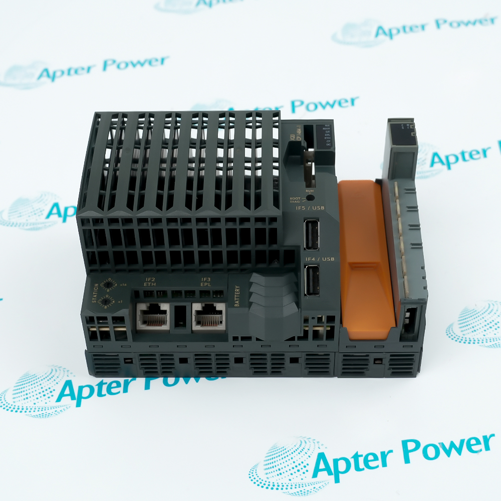
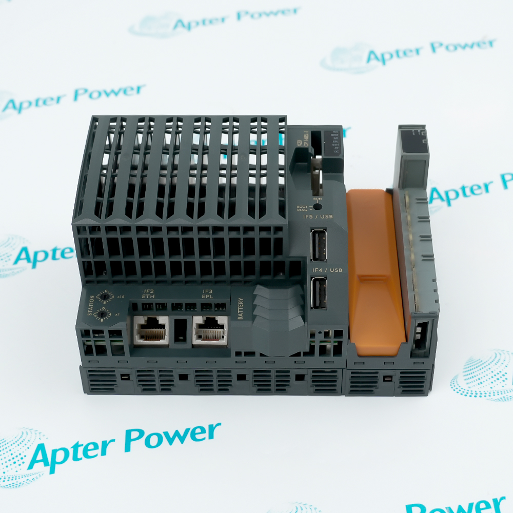
B&R X20DO4529 provides four individually isolated relay changeover outputs for 30 VDC or 115 VAC control circuits. It connects discrete field loads to an X20 station while keeping each output channel isolated from the other channels and the bus.

Ask our team:

Get a quick price for: X20DO4529
Quantity*
Upload (gif, jpg, jpeg, png, bmp, doc, docx, xls, xlsx, ppt, pdf, csv)
For more information on how your data is processed and stored by Apterpower please read our privacy policy.

Technical specifications for X20DO4529

Technical specifications for X20DO4529

  • Manufacturer:
    B&R
  • Product Category:
    PLC Systems
  • Spare Part Number:
    X20DO4529
  • Estimated shipping dimensions:
    9.5x5.7x1.2cm
  • Weight:
    0.02 kg
  • Tariff Code:
    8537101190
  • Counliy of origin:
    Austria
  • Output channels:
    4 relay changeover outputs
  • Nominal voltage:
    30 VDC / 115 VAC
  • Nominal output current:
    1 A at 30 VDC / 0.5 A at 115 VAC
  • Maximum switching voltage:
    110 VDC / 125 VAC
  • Switching delay:
    <=4 ms on; <=4 ms off
  • Electrical isolation:
    Channel-to-channel, channel-to-bus and channel-to-I/O supply
  • Bus power:
    0.8 W
  • B&R ID code:
    0x20D9
  • Protection rating:
    IP20
  • Operating temperature:
    -25 to 60 C horizontal; -25 to 50 C vertical
  • Required terminal block:
    X20TB12
  • Required bus module:
    X20BM11 or X20BM15

Information

Information

Overview Manuals Common Applications Product Precautions
B&R X20DO4529 provides four individually isolated relay changeover outputs for 30 VDC or 115 VAC control circuits. It connects discrete field loads to an X20 station while keeping each output channel isolated from the other channels and the bus.
  • Switches four independent field circuits with changeover contacts
  • Separates each relay channel from the remaining outputs and the X20 bus
  • Reports module and output status through LEDs and software diagnostics
  • Supports DC and mains-frequency AC control duties with external load suppression

Install B&R X20DO4529 with an X20TB12 terminal block and X20BM11 or X20BM15 bus module. Select external suppression for AC or DC loads and prove every relay channel against the configured output state before release.

Important Notice: Confirm B&R X20DO4529, terminal hardware, field wiring, installed accessories and current B&R documentation before commissioning.

Apter Power B&R X20DO4529 Manuals and Guides
Apter Power B&R X20DO4529 Product and System Technical Reference PDFB&R X20DO4529 Official Data Sheet V3.20 PDF

Important Notice: The first document is an Apter Power model-specific technical reference; the second is the B&R official data sheet identified in the manufacturer source record.

Isolated interposing relay duties
B&R X20DO4529 separates four commanded loads where each circuit needs its own changeover contact.
Valve and contactor command
The module switches documented DC or AC control coils through externally protected relay contacts.
Mixed-potential panel outputs
Single-channel isolation permits independent field circuits within the approved voltage limits.
X20 machine-control stations
Status LEDs and software diagnostics support output commissioning and maintenance in an X20 node.
Read the applicable B&R instructions before work. Verify B&R X20DO4529 and the installed X20 System configuration.
1
Confirm the complete X20DO4529 marking and the assigned four output circuits before work.
2
Isolate every external field voltage because the relay circuits can carry potentials independent of the X20 bus.
3
Use X20TB12 with X20BM11 or X20BM15 and verify terminal coding before insertion.
4
Keep each load within the documented voltage, current and switching-capacity limits.
5
Fit an RC network or VDR on AC inductive loads and an inverse diode, RC network or VDR on DC inductive loads.
6
Do not rely on internal contact suppression because X20DO4529 provides none.
7
Record contact state and field voltage on all four channels during controlled commissioning.
8
Prove safe de-energization and the expected changeover action before returning the machine to service.

Revisions

Revisions

Revision Part #

Also known as

Data sheet X20DO4529
B&R version 3.20, 2024-10-01

Alternative Names

Alternative Names

B&R X20DO4529

Technical notes

Technical notes

Install B&R X20DO4529 with an X20TB12 terminal block and X20BM11 or X20BM15 bus module. Select external suppression for AC or DC loads and prove every relay channel against the configured output state before release.

FAQS

  • How are the four B&R X20DO4529 relay channels electrically separated?
    B&R specifies each channel as isolated from the other channels, the bus and the I/O power supply.
  • Which loads fit the B&R X20DO4529 nominal contact ratings?
    The documented nominal ratings are 1 A at 30 VDC and 0.5 A at 115 VAC, subject to the stated switching-capacity limits.
  • What external suppression is required when B&R X20DO4529 switches an inductive load?
    For AC loads use an RC combination or VDR; for DC loads use an inverse diode, RC combination or VDR.
  • Why must a B&R X20DO4529 replacement retain the terminal and bus modules?
    The official data sheet requires an X20TB12 terminal block and an X20BM11 or X20BM15 bus module for the installed slice.
  • How quickly should B&R X20DO4529 contacts change state?
    Both the 0-to-1 and 1-to-0 switching delays are specified at no more than 4 ms.
  • Which contact-life records matter for B&R X20DO4529 maintenance?
    B&R lists at least 100,000 electrical operations and 50 million mechanical operations at 3 Hz; the actual load history remains important.
  • What diagnostics can confirm a commanded B&R X20DO4529 output?
    The module provides per-output LED indication plus operating-state and module-status reporting.
  • How should B&R X20DO4529 be accepted after wiring changes?
    Energize each documented field circuit under controlled conditions, compare the command with contact state and prove the intended safe state on de-energization.
Trusted by 5,000+ plants worldwide | Backed by our vast inventory of top-tier control parts, modules and cards, fast shipments are dispatched to cover your urgent needs. ABOUT US >>
Disclaimer: We are not an authorized distributor or distributor of the product manufacturer of this website, The product may have older date codes or be an older series than that available direct from the factory or authorized dealers. Because our company is not an authorized distributor of this product, the Original Manufacturer`s warranty does not apply.While many DCS PLC products will have firmware already installed, Our company makes no representation as to whether a DSC PLC product will or will not have firmware and, if it does have firmware, whether the firmware is the revision level that you need for your application. Our company also makes no representations as to your ability or right to download or otherwise obtain firmware for the product from our company, its distributors, or any other source. Our company also makes no representations as to your right to install any such firmware on the product. Our company will not obtain or supply firmware on your behalf. It is your obligation to comply with the terms of any End-User License Agreement or similar document related to obtaining or installing firmware.

Product Browsing History

We’re Here When You Need Us

From product insights to customer service needs, our experienced service team will focus on getting you what you need quickly

Enquire

Complete our online form.

Call Us

Speak to one of our team.

Live Chat

Send us a message.