Speak to a sourcing specialist
sales13@apterpower.com

6DD1611-0AG0

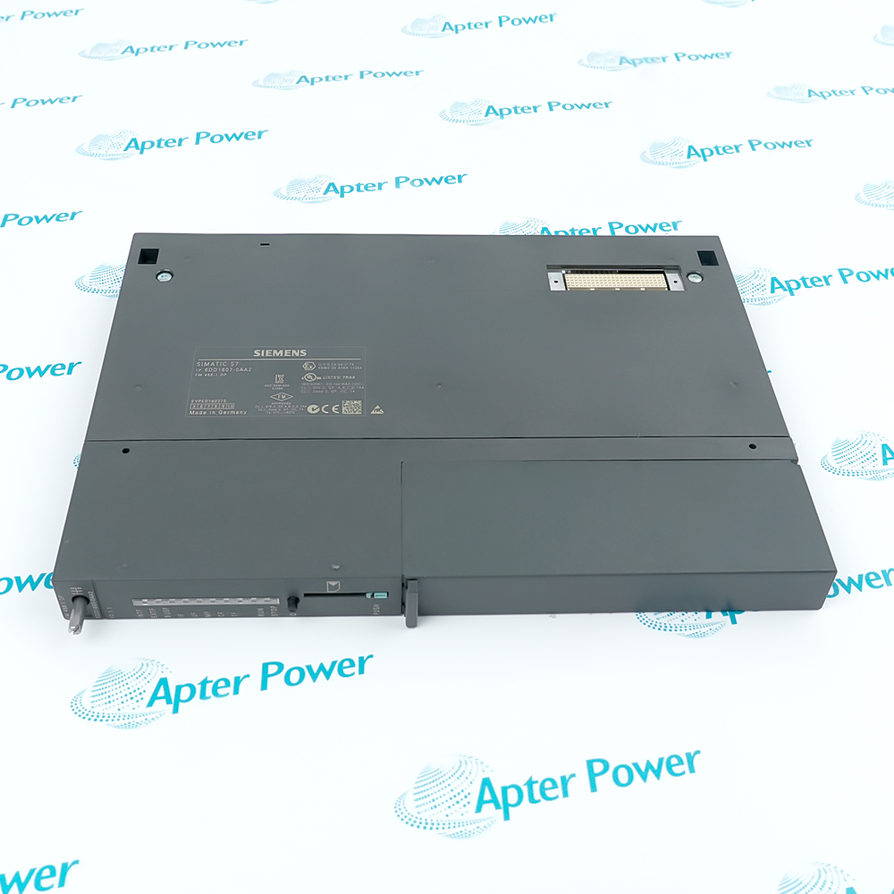
Coupling Memory Module
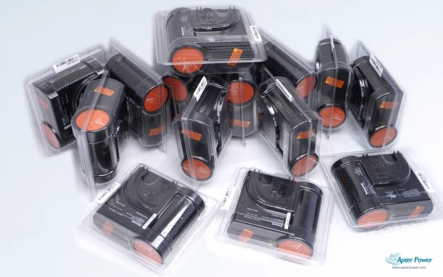
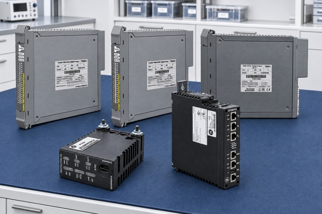
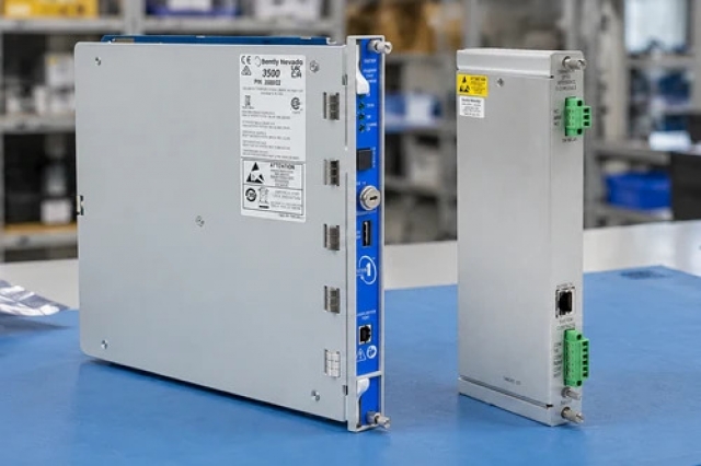
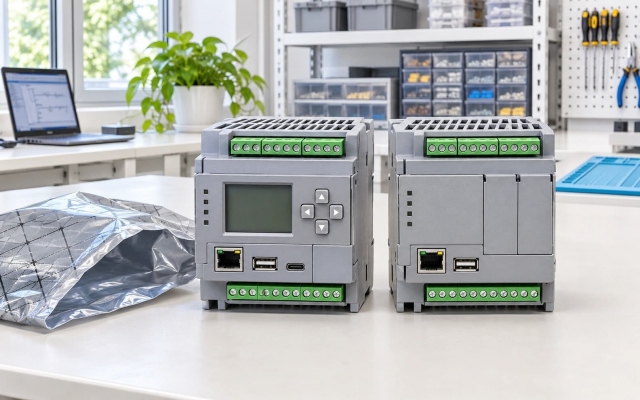
Product image is representative; revision or series may vary. Contact us to request a specific version.

Product Describe:

Siemens 6DD1611-0AG0 provides the MM4 shared-memory interface for data exchange between CPU modules in a SIMADYN D subrack. It connects to both backplane buses and includes a system-error relay.
  • Manufacturer part number
    6DD1611-0AG0
  • Shipping
    Swift global dispatch
  • Condition
    New, original product
  • Shipping size (est.)
    2cm x 26.1cm x 26.1cm
  • Country of Origin
    USA
Get a quick price for 6DD1611-0AG0
E-mail *
Mobile
Company
Content *
Quantity *
Upload (gif, jpg, jpeg, png, bmp, doc, docx, xls, xlsx, ppt, pdf, csv)
For more information on how your data is processed and stored by Apterpower please read our privacy policy

What happens after you enquire

  • 0

    Review your reference

    Send the complete 6DD1611-0AG0 reference, label photographs and required quantity. Check the MM4 marking, bus connectors and system-error relay connection.

  • 1

    Confirm the offer

    Review the offered 6DD1611-0AG0 execution, condition and included items. Confirm coupling memory module and any separately listed terminal accessories in the quotation.

  • 2

    Arrange dispatch

    Swift global dispatch. Confirm quantity, dispatch date and delivery details for 6DD1611-0AG0 in the quotation.

  • Match the complete marking

    Match the complete Siemens 6DD1611-0AG0 marking and actual installed configuration. Check the MM4 marking, bus connectors and system-error relay connection.

  • Check the offered item before ordering

    Compare offered-unit photographs, interfaces and included items with the installed 6DD1611-0AG0 and its applicable installation requirements.

Technical specifications for 6DD1611-0AG0

  • Manufacturer:
    Siemens
  • Product Category:
    DCS Systems
  • Spare Part Number:
    6DD1611-0AG0
  • Weight:
    0.3 kg
  • Tariff Code:
    8537101190
  • Shared-memory capacity:
    2 × 2 MB
  • Backplane interfaces:
    L bus and C bus
  • Occupied slots:
    1
  • Supply voltage:
    5 V DC nominal
  • Supply tolerance:
    4.75–5.25 V
  • Typical current:
    800 mA
  • System-error contact voltage:
    60 V DC maximum
  • System-error contact current:
    0.5 A maximum
  • System-error switching power:
    20 W maximum

Information

Overview Downloads Applications / Compatibility Product Precautions
  • Siemens 6DD1611-0AG0 supports multi-CPU coordination by making communication memory available between processors while retaining the required position in the subrack bus sequence.
Processor coordination: Shared data exchange between CPU modules
Bus integration: Memory and termination for both backplane buses
Retention path: Subrack battery supports memory during power loss
The MM4 is used where several CPU modules exchange data in one subrack or share access to a communication interface. Install it between the first and second CPU modules; its position is part of the communication architecture.

The two bus memories support the configured data exchange. The subrack backup arrangement preserves data during power loss, while the system-error relay provides a separate hardware indication that must be interpreted with the CPU states.

The MM4 does not provide the MM3 radio-clock function. Where both large shared memory and a buffered clock are required, the supported combined arrangement uses the appropriate separate modules and configuration.
Controller platform reference: SIMADYN D L-bus and C-bus. Follow the applicable installation instructions and approved design.
Technical and service documents for Siemens 6DD1611-0AG0, covering the applicable hardware arrangement and engineering verification.
Original manufacturer pages retain their technical context. Use the Apter Power guide with the applicable manufacturer instructions and approved installation design.
System and supply context: Siemens 6DD1611-0AG0 serves the SIMADYN D L-bus and C-bus arrangement. Evaluate the full connected signal or control path when selecting companion hardware.

Application scope: The applications below describe the installed measurement or control path. Select compatible companion equipment; accessories are included only when expressly itemized.
Prepare Siemens 6DD1611-0AG0 for its configured installation using these checks.
Map the CPU memory relationship

Record the first and second CPU positions, MM4 placement and configured interprocessor connections. Identify any communication interface accessed by more than one CPU.

Protect the retained data

Back up the configuration and assess the subrack battery path. Plan the power interruption with the process secured and preserve any application values required for restart.

Restore bus and relay connections

Follow the SIMADYN D installation procedure, preserving the MM4 slot relationship and connector engagement. Reinstate the system-error contact wiring without changing its external load.

Exercise CPU data exchange

Start the system under controlled conditions and stimulate the configured data exchanges. Check changing values at every intended receiver and review associated CPU diagnostics.

Verify fault and recovery behavior

Test the approved system-error response and the intended restart sequence. Record the final rack map, communication checks and backup condition for the maintenance handover.

Configuration handover

Retain the final 6DD1611-0AG0 identity, tested settings and accepted channel or system response for subsequent maintenance.

Alternative Names

Siemens 6DD1611-0AG0

Technical notes

Slot relationship: The shared-memory module belongs between the first and second CPU modules. Preserve that relationship when altering the rack layout.

Clock-function separation: The MM4 supplies memory and a system-error relay. A buffered radio-clock requirement belongs to the separate MM3 arrangement and its CPU configuration.

Backup and error contact: Assess subrack battery continuity separately from normal supply health. Test the error contact with its external circuit within all voltage, current and power limits.


FAQ View All FAQ

  • Why does the rack position of 6DD1611-0AG0 matter to a multi-CPU system?
    It must sit between the first and second CPU modules. Preserve that bus relationship rather than moving the module to an arbitrary unused slot.
  • Does 6DD1611-0AG0 include the radio clock associated with MM3 hardware?
    No. MM4 supplies the larger shared memory and system-error relay; the MM3 clock is a separate function and must not be assumed to exist on MM4.
  • Can 6DD1611-0AG0 replace a memory module without checking the configured CPU connections?
    No. Review the shared-data organization and each CPU connection, including any common access to a communications interface.
  • What should be checked if data is lost from 6DD1611-0AG0 after a power interruption?
    Inspect the subrack backup path and battery condition in addition to the normal supply. A healthy powered rack does not prove backup continuity.
  • How should the error relay on 6DD1611-0AG0 be incorporated into an external circuit?
    Respect its voltage, current and switching-power limits simultaneously, and validate the contact interpretation against the system fault response.
  • Why is a memory-capacity comparison insufficient when selecting 6DD1611-0AG0?
    Bus interfaces, slot relationship, backup behavior and configured data exchange also determine suitability. Capacity alone does not establish interchangeability.
  • What test can reveal an incomplete data path through 6DD1611-0AG0?
    Exercise the configured exchanges between the relevant CPUs and check that each receiver obtains the intended changing values, rather than accepting only a healthy power indication.
  • How should an MM3 and 6DD1611-0AG0 be assessed when both are installed?
    Confirm that the application uses MM4 for shared memory and the separate MM3 for its supported clock function; retain the intended CPU configuration for both roles.
SPEAK TO OUR TEAM
Let’s find the right solution for you.
Send us the part number, quantity and delivery destination. Our team will help confirm availability and lead time.
  • Whatsapp: +86 18030235313

    Send us a message.
  • sales13@apterpower.com

    Complete our online form.
  • +86 18030235313

    Speak to our team in your native language.