-
Match the complete marking
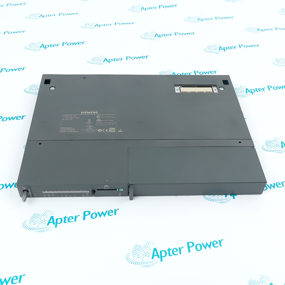
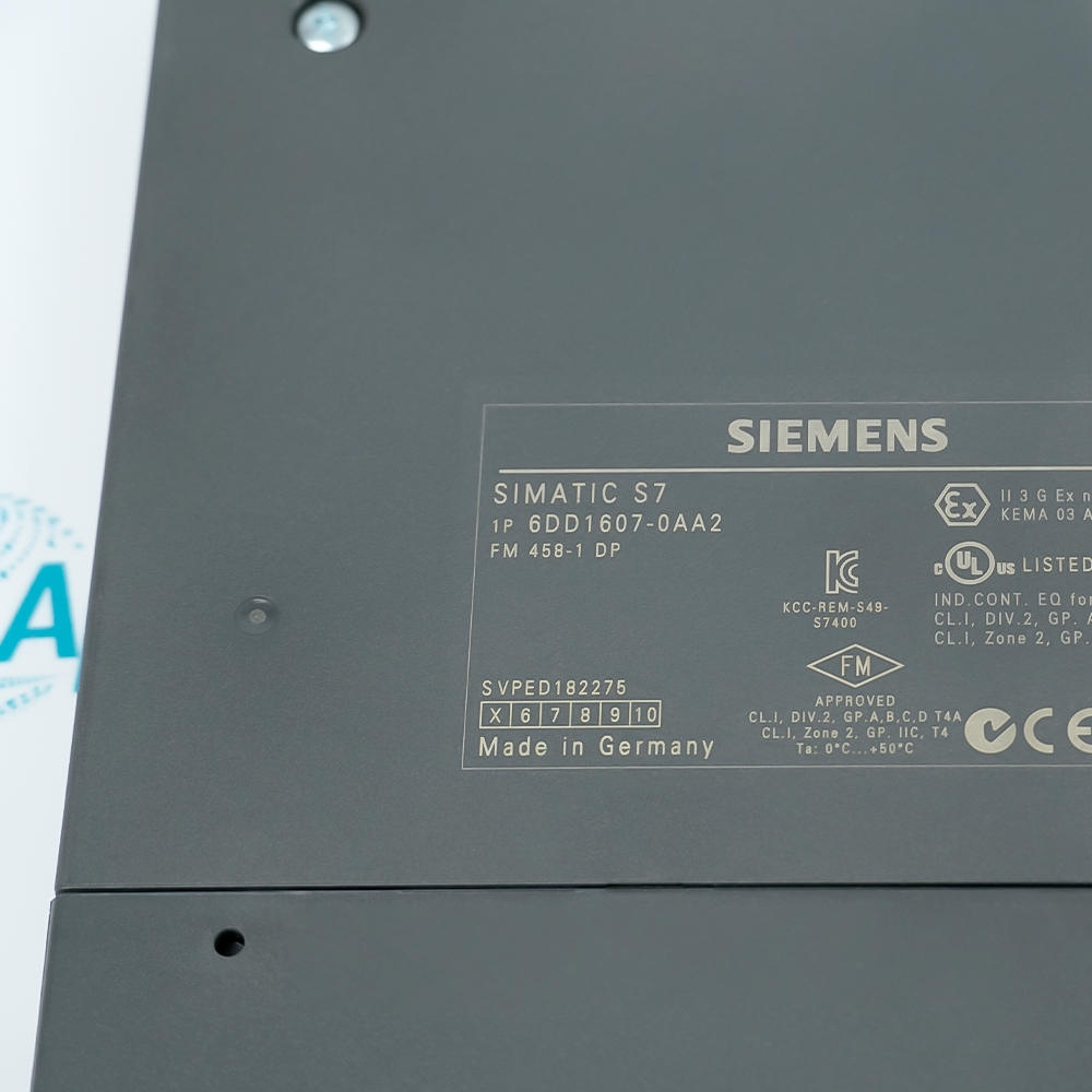
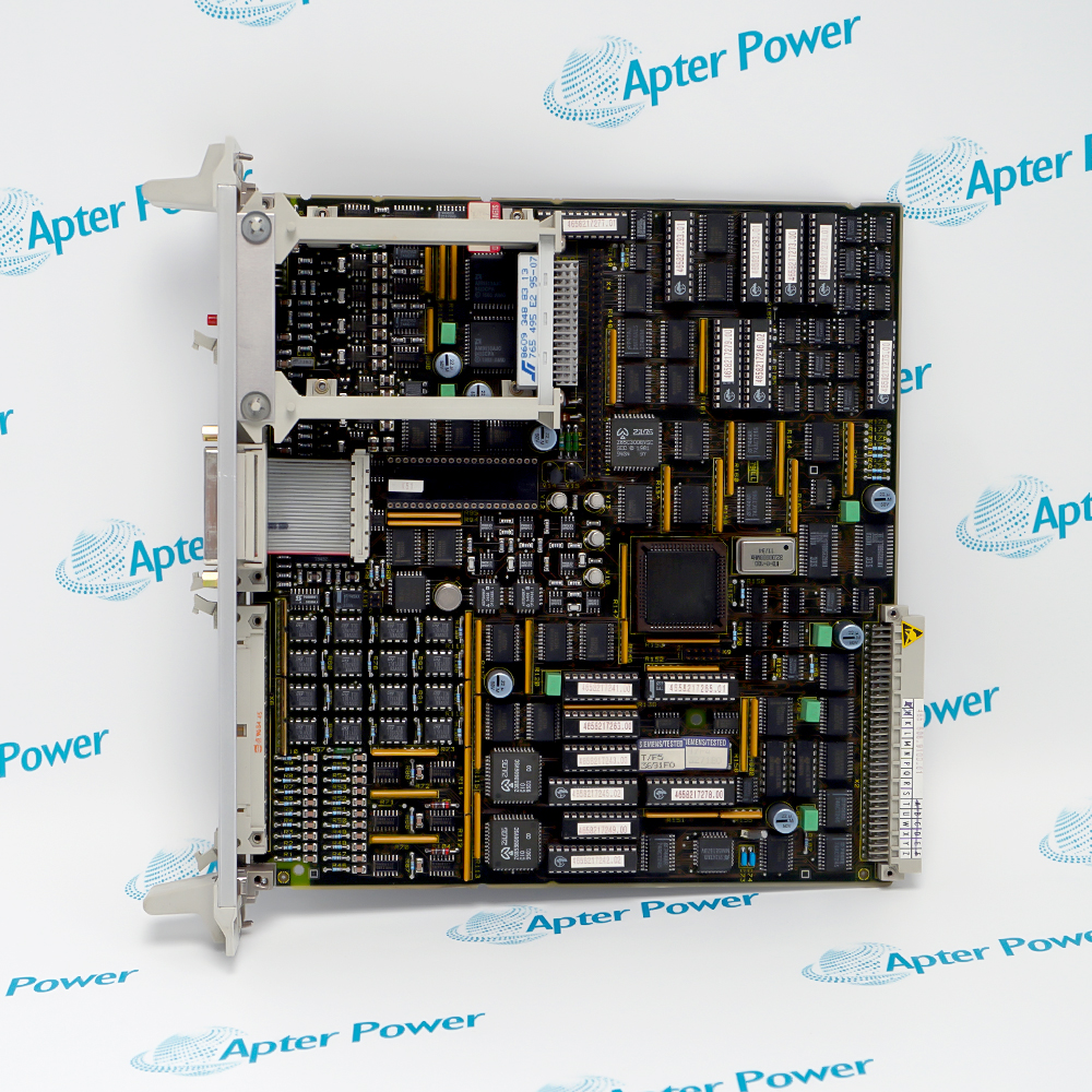
Match the complete Siemens 6DD1607-0AA2 marking, hardware execution and connection arrangement to the installed position before approving the order.
-
Check the offered item before ordering
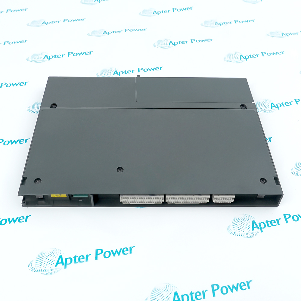
Request clear photographs of the offered 6DD1607-0AA2 and ask your maintenance team to compare its markings and interfaces with the installed equipment and applicable Siemens instructions.
Technical specifications for 6DD1607-0AA2
-
Manufacturer:Siemens
-
Product Category:PLC Systems
-
Spare Part Number:6DD1607-0AA2
-
Weight:1.04 kg
-
Tariff Code:8537101190
-
Backplane supply range:4.8-5.25 V DC
-
Typical current:1.5 A
-
Maximum current:3 A
-
Digital inputs:8 at X2
-
Rated input voltage:24 V DC
-
LOW input level:-1 to +6 V
-
HIGH input level:13.5 to 33 V
-
Typical HIGH current:3 mA at 24 V
-
Maximum rising-edge delay:5 microseconds
-
Clock resolution:500 ms
-
Maximum backup current:15 microamperes
-
Input isolation:Via optional interface modules; not inherent
Information
- Siemens 6DD1607-0AA2 places fast application processing beside the S7-400 control system, with response determined by the configured tasks and complete signal path.
Timing relationship: Configured tasks and coordinated interfaces
Expansion boundary: Supported modules and application engineering
Time-critical behavior depends on task scheduling, application configuration and connected interfaces. A fast electrical input specification does not establish the complete closed-loop response of the machine. Evaluate acquisition, computation and output paths together.
Retained data and the application-loading arrangement must be preserved during service. Hardware identity, configured communication and the supported expansion modules form one baseline; a mechanically fitting replacement should not be accepted without that comparison.
6DD1607-0AA2 Original Technical Excerpt
The original technical excerpt supports 6DD1607-0AA2 configuration review. The separate Apter Power field guide organizes practical diagnostic checks. PDF · 2 pages.6DD1607-0AA2 Installation & Verification Guide
Apter Power engineering guide for the installed signal, power or communication path and controlled acceptance. PDF · 5 pages.
Application scope: The following uses describe supported engineering roles; they do not establish interchangeability with another model or remove application-specific validation.
Fast control tasks
Run the supported engineered application in the S7-400 arrangement.Digital event acquisition
Use the local inputs within their specified electrical conditions.PROFIBUS-linked control
Integrate the configured DP communication and timing relationship.Application-module maintenance
Restore the approved program and expansion-hardware baseline.
Capture the FM application, task relationships, retained state and expansion-module identities with the S7-400 project. Identify the signals whose timing is critical and define their observed start and end points. Include the communication schedule where it participates in the control path rather than treating module input delay as the whole response.
Check the backplane supply budget and the field-input reference arrangement. Compare actual LOW and HIGH voltages at the input terminals with the guaranteed ranges. Assess isolation according to the installed interface hardware; do not presume separate galvanic boundaries solely from the presence of multiple terminals.
Restore the approved loading method, retained values and peripheral configuration with the process controlled. Inspect startup and application diagnostics before stimulating inputs. Verify configured communications and timing relationships before enabling functions that depend on coordinated task execution.
Measure a representative event from field transition through application processing to the final output response. Record the operating configuration and load during the test. Compare the complete observed response with the application requirement instead of adding an unsupported timing guarantee to the module specification.
Perform the approved restart and retained-state checks, then restore process authority in the defined sequence. Confirm that peripheral data and application timing remain correct after the temporary test setup is removed. Archive the resulting project and timing observations with the exact hardware arrangement.
Use the exact hardware execution with the supported system configuration and installation conditions.

Alternative Names
Technical notes
Configuration baseline: Keep the installed SIMATIC S7-400 arrangement aligned with the complete 6DD1607-0AA2 reference and its assigned system role.
Acceptance boundary: Compare the electrical or communication response with the intended application outcome before releasing maintenance controls.
Technical reference: Siemens product data sheet, 6DD1607-0AA2. Use the exact hardware execution with the supported system configuration and installation conditions.

FAQ View All FAQ
-
Why does the input delay of 6DD1607-0AA2 not equal total machine response time?Input conditioning is only one stage. Task execution, communication and the output device add their own delays. Measure the complete signal path under the intended configuration before assigning a response guarantee to the machine.
-
What should be preserved before replacing 6DD1607-0AA2 in a fast-control application?Retain the application, hardware configuration, communication settings and expansion-module identities. Include retained operating data where required. Restoring the module without its application baseline can leave a physically complete but nonfunctional system.
-
How should input-level problems on 6DD1607-0AA2 be diagnosed?Measure the signal at the module against the specified LOW and HIGH ranges, including the return reference. Compare the electrical transition with the task-level observation. A field-device LED does not establish a valid voltage at the module.
-
Can all 6DD1607-0AA2 digital inputs be assumed galvanically isolated?No. Use the isolation details for the specific interface and expansion arrangement. Check common references and approved wiring before connecting independently referenced field circuits; isolation must not be inferred from the module category.
-
Why must the PROFIBUS timing configuration of 6DD1607-0AA2 be retained?Equidistant operation and task relationships depend on the configured application. Changing network timing can alter control behavior even when communication remains active. Verify timing-dependent functions after any authorized bus or task change.
-
What distinguishes an application-loading fault from a failed 6DD1607-0AA2 input?Check startup diagnostics and application execution first, then apply a known input stimulus. A healthy input cannot be observed by a task that did not load or start correctly. Separate the software baseline from the electrical test.
-
How should expansion hardware used with 6DD1607-0AA2 be assessed during replacement?Compare exact expansion-module types and their configured roles with the retained project. Validate each affected signal path. The main module identity alone does not establish compatibility of every attached peripheral.
-
What validates 6DD1607-0AA2 after a controlled restart?Confirm the intended application starts, retained values are correct and configured communications are healthy. Then exercise representative inputs through to the final controlled response. Startup indication without an end-to-end test leaves timing and mapping errors unresolved.
Supporting new and legacy automation
-
Please try to be as accurate as possible with your search.
-
We can quote you on 1000s of specialist parts, even if they are not listed on our website.
-
We can't find any results for “”.
Related cases and sourcing guidance
View all case studiesYou May Also Like
Product Browsing History
-
Whatsapp: +86 18030235313
Send us a message. -
sales13@apterpower.com
Complete our online form. -
+86 18030235313
Speak to our team in your native language.