Speak to a sourcing specialist
sales13@apterpower.com

531X307LTBAKG1

LAN I/O Terminal Board
Product image is representative; revision or series may vary. Contact us to request a specific version.

Product Describe:

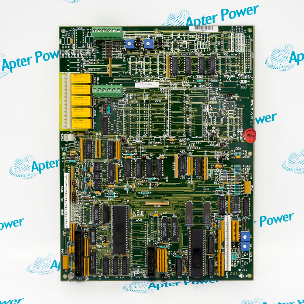
GE 531X307LTBAKG1 is a LAN I/O terminal board for the DC2000 drive control family, providing labeled field-input and output terminations through the 531X307LTB board design.
  • Manufacturer part number
    531X307LTBAKG1
  • Shipping
    Swift global dispatch
  • Condition
    New, original product
  • Shipping size (est.)
    28.6cm x 8cm x 2.5cm
  • Country of Origin
    USA
Get a quick price for 531X307LTBAKG1
E-mail *
Mobile
Company
Content *
Quantity *
Upload (gif, jpg, jpeg, png, bmp, doc, docx, xls, xlsx, ppt, pdf, csv)
For more information on how your data is processed and stored by Apterpower please read our privacy policy

What happens after you enquire

  • 0

    Review your reference

    Send the complete 531X307LTBAKG1 marking, installed revision, quantity and system configuration with your enquiry.

  • 1

    Confirm the offer

    Check that the quotation identifies 531X307LTBAKG1, its offered condition, included parts and dispatch date.

  • 2

    Arrange dispatch

    Confirm the delivery details and receive tracking information when shipment is arranged.

  • Match the complete marking

    Include 531X307LTBAKG1 and every visible revision or serial identity in your enquiry. Keep the same complete reference on the quotation.

  • Check the offered item before ordering

    Request available label and connector photos. Have your maintenance team compare the offered 531X307LTBAKG1 with the installed equipment and applicable GE documentation.

Technical specifications for 531X307LTBAKG1

  • Manufacturer:
    General Electric
  • Product Category:
    General Automation
  • Spare Part Number:
    531X307LTBAKG1
  • Weight:
    0.26 kg
  • Tariff Code:
    8537101190
  • Board design:
    531X307LTB LAN I/O terminal board
  • Board group:
    G1 family; complete KG1 revision marking
  • Control inputs:
    Eight labeled IN1–IN8 on the observed board
  • Relay outputs:
    Seven labeled OT1–OT7 on the observed board
  • Output contacts:
    Form C, non-fused, in the G1 family manual
  • Output rating, family:
    0.6 A at 125 V AC / 110 V DC; 2 A at 30 V DC
  • Input AC range, family:
    24–230 V AC, 60 Hz; 115–230 V AC, 50 Hz
  • Input DC range, family:
    24–250 V DC
  • Terminal wire, family:
    28–14 AWG
  • Interconnection, family:
    26-conductor ribbon, 20 ft maximum
  • Drive interface:
    External contactors, indicators, pushbuttons and interlocks

Information

Overview Downloads Applications / Compatibility Product Precautions
  • GE 531X307LTBAKG1 sits at the DC2000 drive's field-wiring boundary, bringing control inputs and relay outputs to accessible terminal rows.
Wiring handover: Photograph and label every field conductor before removal
Circuit separation: Trace input, relay and ribbon-cable paths independently
Acceptance test: Prove each used field point against the drive logic after fitting
The 531X307LTB G1 family connects external control devices such as pushbuttons, interlocks, contactors and indication lamps to the drive control electronics. The observed KG1 board has eight IN terminals and seven OT relay-output positions; the exact terminal schedule must follow the installed cabinet drawing.

The GE family manual describes seven low-current, non-fused Form C outputs and pilot connections for higher-current relay arrangements. Its stated contact ratings are 0.6 A at 125 V AC or 110 V DC, and 2 A at 30 V DC. Do not use those family figures as permission to exceed the rating of the actual connected device or its external protection.

The original LTB design uses plug and ribbon interconnections to the drive controller and field termination rows for external wiring. The family manual gives 28–14 AWG terminal conductors and a 20 ft maximum for the 26-conductor interconnection ribbon. Keep ribbon cables apart from power conductors to reduce input leakage and false indications.
Controller platform reference: GE DC2000 LAN I/O. Match the actual terminal schedule and revision.
Technical downloads for General Electric 531X307LTBAKG1: a product-specific Apter Power technical reference and an Apter Power installation and commissioning guide.
Both documents are prepared by Apter Power for the offered model. Check the complete marking and installed system before applying the engineering guidance.
Before replacing 531X307LTBAKG1, isolate the drive and external field supplies, retain the as-found terminal map and prove every used I/O path under controlled conditions.
Isolate every field source

De-energize drive and separately supplied field circuits. Confirm safe voltage at input and output terminal rows before handling the board.

Preserve terminal identity

Label conductors at IN1–IN8 and OT1–OT7; record polarity, commons and external protection before disconnecting any wire.

Control output loading

The G1 family Form C contacts are non-fused. Check the connected load and provide external protection appropriate to the actual circuit.

Separate ribbon and power

Route the controller ribbon connection away from power conductors; capacitive coupling or leakage can hold inputs in an unintended ON state.

Match the KG1 board

Compare full board marking, connector orientation and revision with the installed hardware. Do not assume another LTB suffix is drop-in compatible.

Prove inputs and outputs

After reconnection, stimulate each used field input and command each assigned output in a safe test state, recording controller indication and actuator response.

Alternative Names

GE 531X307LTBAKG1 GE Drive Systems 531X307LTBAKG1 General Electric 531X307LTBAKG1

Technical notes

I/O relationship: The 531X307LTB G1 design interfaces DC2000 control electronics with field switches, pilot devices and relay circuits. Match the observed IN1–IN8 and OT1–OT7 terminals to the original wiring drawing.

Circuit limits: The family manual specifies non-fused Form C outputs and input/terminal limits. Confirm the exact KG1 board revision and connected load before applying the family ratings; protect external circuits separately.

Technical reference: GE DC2000 Digital Adjustable Speed Drive Instruction Manual, GEH-6005. Its 531X307LTB G1 discussion is family-level evidence; the KG1 revision is checked against the offered board and installed drive record.


FAQ View All FAQ

  • How should a field signal be traced through 531X307LTBAKG1 during fault isolation?
    Trace the external contact or device to its terminal, then through the board's ribbon interconnect to the DC2000 controller indication or output command. Use the cabinet drawing for the actual assignment; the board is the field-wiring boundary rather than the source of drive logic.
  • How should unused and used field points on 531X307LTBAKG1 be documented?
    Record the observed IN1–IN8 and OT1–OT7 terminal labels against the cabinet wire schedule and identify which points are actually populated. Do not infer a live signal from the physical point count; prove each used path under a safe drive state.
  • What protection is required around the relay outputs of 531X307LTBAKG1?
    The G1 family manual describes non-fused Form C relay contacts. Review the external circuit protection, load category and connected device current before energizing the KG1 installation; the board does not supply a fuse for each output.
  • How should a proposed load be checked against the outputs of 531X307LTBAKG1?
    Compare the actual device load and switching duty with the family limits of 0.6 A at 125 V AC or 110 V DC and 2 A at 30 V DC. Confirm the fitted KG1 board and cabinet protection before applying these family values to a specific circuit.
  • How should input voltage be checked for 531X307LTBAKG1?
    The LTB family manual provides AC and DC input ranges, but the actual field voltage must be taken from the cabinet schematic. Verify every input source and common before reconnecting the KG1 terminals.
  • Why should ribbon wiring for 531X307LTBAKG1 be separated from power cables?
    The GE manual warns that capacitive coupling and leakage can make an I/O input remain ON. Preserve the 26-conductor interconnect route, keep it away from power wiring and investigate any input that does not drop out.
  • Can another 531X307LTB revision replace 531X307LTBAKG1 without review?
    Do not infer interchangeability from the shared base name. Compare the complete KG1 board identity, connector positions, input circuits and output wiring against the installed drive before substitution.
  • What should be tested after installing 531X307LTBAKG1?
    Verify ribbon connections and every used IN/OT terminal. Under a safe drive state, prove the external device, terminal point, controller indication and commanded output path one by one.
Manufacturers

Product Browsing History

Revisit the products you recently viewed on Apter Power.
SPEAK TO OUR TEAM
Let’s find the right solution for you.
Send us the part number, quantity and delivery destination. Our team will help confirm availability and lead time.
  • Whatsapp: +86 18030235313

    Send us a message.
  • sales13@apterpower.com

    Complete our online form.
  • +86 18030235313

    Speak to our team in your native language.