-
Match the complete marking
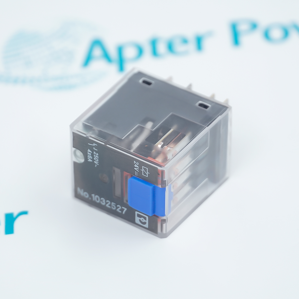
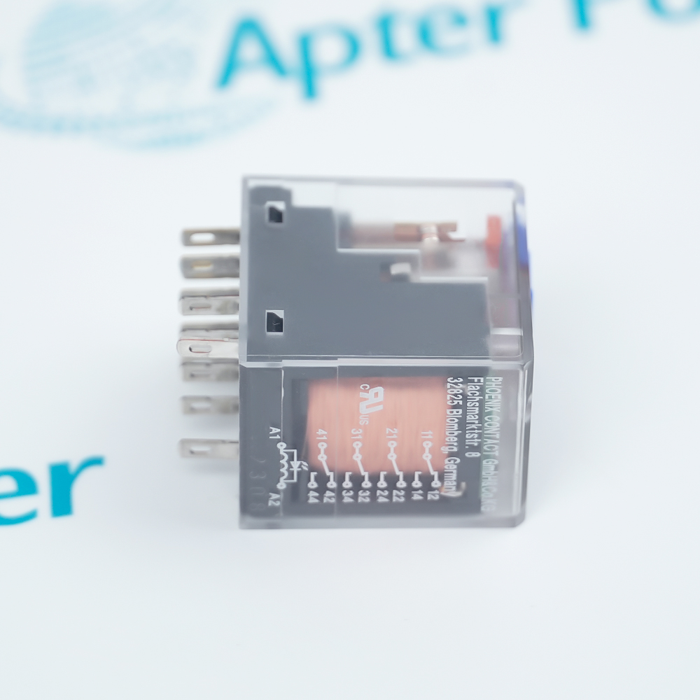
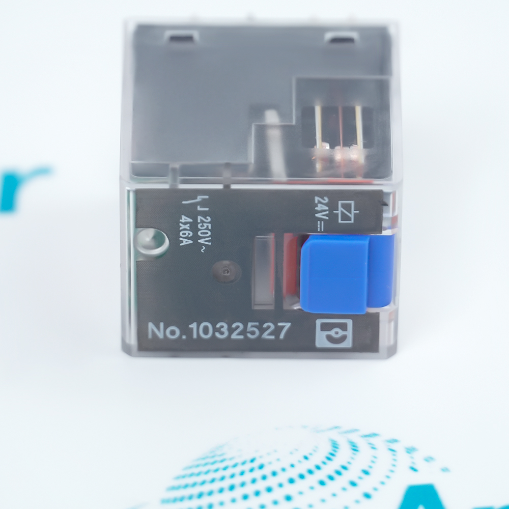
Include REL-IR-BL/L-24DC/4×21 1032527 and any revision or assembly number visible on the item. Keep the exact reference on your enquiry and quotation.
-
Check the offered item before ordering
Request available label and connector photos. Have your maintenance team compare the offered REL-IR-BL/L-24DC/4×21 1032527 with the installed equipment and applicable Phoenix Contact documentation.
Technical specifications for REL-IR-BL/L-24DC/4×21 1032527
-
Manufacturer:Phoenix Contact
-
Product Category:General Automation
-
Spare Part Number:REL-IR-BL/L-24DC/4×21 1032527
-
Weight:0.95 kg
-
Tariff Code:8537101190
-
Product type:Plug-in industrial relay
-
Article number:1032527
-
Contact arrangement:4 changeover contacts
-
Contact material:AgNi
-
Nominal coil voltage:24 VDC
-
Input voltage range:19.2–46.8 VDC at 20 °C
-
Coil operation:Monostable, polarized
-
Typical input current:32 mA at nominal voltage
-
Typical response / release:15 ms / 10 ms
-
Maximum switching voltage:250 VAC/DC
-
Minimum switching condition:12 V at 10 mA
-
Limiting continuous current:6 A
-
Maximum NO inrush:12 A for 20 ms
-
Resistive interrupting rating:144 W at 24 VDC; 1500 VA at 250 VAC
-
Relay protection / location:RT II / installation location ≥ IP54
-
Operating and storage temperature:-40 to +70 °C
-
Maximum altitude:2000 m
-
Insulation classification:Basic insulation; category III; pollution degree 2
-
Status indication:Yellow LED and mechanical position indicator
-
Mounting:Plug-in; any orientation
Information
- Phoenix Contact REL-IR-BL/L-24DC/4×21 1032527 switches four contact circuits in an industrial relay arrangement and provides a test button, status LED and mechanical position indication.
Coil supply: 24 VDC nominal, polarized monostable operation
Local indication: Test button, yellow LED and mechanical position indicator
The contacts have a 6 A limiting continuous current and a maximum switching voltage of 250 VAC/DC. The minimum switching condition is 12 V at 10 mA, while the normally open contacts permit a maximum 12 A inrush for 20 ms. Resistive-load interrupting ratings include 144 W at 24 VDC and 1500 VA at 250 VAC; the DC capability changes with voltage and must be checked against the actual circuit. Maximum current and maximum voltage are separate limits and are not permission to switch every load at their product.
The relay is classified RT II and requires an installation location protected to at least IP54. Operating and storage temperatures are -40 to +70 °C, with an altitude limit of 2000 m. The coil-to-contact insulation is basic insulation, with overvoltage category III and pollution degree 2; the relay is not suitable for separating SELV/PELV circuits from other circuits. Plug-in mounting supports any orientation and zero-spacing rows, subject to the selected socket and enclosure arrangement.
-
Phoenix Contact REL-IR-BL/L-24DC/4×21 1032527 technical reference
Prepared by Apter Power - PDF, 5 pages, 26.2 KB. Technical summary of verified ESSENTIAL edition industrial relays design functions and applicable configuration boundaries. -
Phoenix Contact REL-IR-BL/L-24DC/4×21 1032527 installation planning guide
Prepared by Apter Power - PDF, 5 pages, 25.9 KB. Installation planning, system integration and controlled acceptance checks.
Platform applications: The following applications describe ESSENTIAL edition industrial relays functions. Match the complete REL-IR-BL/L-24DC/4×21 1032527 identity to the installed system before selecting a replacement.
-
Industrial contact switching
Switch four changeover circuits with the specified AgNi contacts. Evaluate the actual load type, current and voltage against the relevant contact ratings. -
24 VDC control circuits
Operate the polarized monostable coil from a compatible 24 VDC control circuit. The 19.2–46.8 VDC range is specified at 20 °C and must retain that condition. -
Local relay diagnostics
Use the yellow LED and mechanical position indication during controlled troubleshooting. The test button can affect connected circuits, so its use belongs within the machine test procedure. -
Socket-based panel assembly
Install the relay in the correct matching socket within an enclosure providing at least IP54. Any-orientation mounting and zero-spacing rows do not replace socket and thermal checks.
Retain REL-IR-BL/L-24DC/4×21 and article 1032527 together. Compare the coil marking and contact arrangement with the installed relay and socket.
Use the polarized 24 VDC coil with the correct connection polarity. Apply the input range only with its stated 20 °C condition and review temperature-dependent operation.
Check switching voltage, continuous current, inrush duration and resistive or inductive load separately. The 12 A inrush limit applies to normally open contacts for 20 ms.
Do not use this relay to separate SELV/PELV circuits from other circuits. Do not mix SELV/PELV and hazardous voltages on adjacent channels or switch different outer conductors.
Use the matching plug-in socket and an installation location rated at least IP54. Keep operating temperature within -40 to +70 °C and altitude at or below 2000 m.
Isolate affected circuits before replacement. Use the test button only under an approved procedure, then verify coil actuation, contact states and machine response before release.
Alternative Names
Technical notes
Installation relationship: The contacts have a 6 A limiting continuous current and a maximum switching voltage of 250 VAC/DC. The minimum switching condition is 12 V at 10 mA, while the normally open contacts permit a maximum 12 A inrush for 20 ms. Resistive-load interrupting ratings include 144 W at 24 VDC and 1500 VA at 250 VAC; the DC capability changes with voltage and must be checked against the actual circuit. Maximum current and maximum voltage are separate limits and are not permission to switch every load at their product.
Configuration: 1032527 identifies the REL-IR-BL/L- 24DC/4X21 single relay. Coil, contact and insulation limits apply to the relay; the matching socket and installation enclosure are separate selection items.
Technical reference: Phoenix Contact 1032527 product data sheet, data status 22 October 2026.

FAQ View All FAQ
-
What contacts does REL-IR-BL/L-24DC/4×21 1032527 provide?It has four changeover contacts made from AgNi. Contact limits must be evaluated for the actual switched load.
-
What coil voltage is required by REL-IR-BL/L-24DC/4×21 1032527?Nominal coil voltage is 24 VDC. The specified input range is 19.2–46.8 VDC at 20 °C; operation is monostable and polarized.
-
What current can REL-IR-BL/L-24DC/4×21 1032527 carry?Limiting continuous contact current is 6 A. The normally open contacts have a maximum inrush rating of 12 A for 20 ms. These limits do not replace load-specific interrupting ratings.
-
What response times apply to REL-IR-BL/L-24DC/4×21 1032527?Typical response time is 15 ms and typical release time is 10 ms. These are typical relay timings rather than guaranteed complete-system response times.
-
What indications are provided by REL-IR-BL/L-24DC/4×21 1032527?It has a yellow bidirectional status LED, a mechanical switch-position indicator and a test button. Operate the test button only under controlled circuit conditions.
-
Can REL-IR-BL/L-24DC/4×21 1032527 separate SELV/PELV circuits?No. The manufacturer specifies basic insulation and states that safe separation of SELV/PELV from other circuits is not guaranteed. Adjacent channels must not mix SELV/PELV with hazardous voltages.
-
Which environmental limits apply to REL-IR-BL/L-24DC/4×21 1032527?Operating and storage temperatures are -40 to +70 °C, altitude is limited to 2000 m, and the installation location must provide at least IP54 protection.
-
How is REL-IR-BL/L-24DC/4×21 1032527 mounted?It uses plug-in mounting with a matching relay socket. Any orientation and zero-spacing rows are permitted for the relay, while socket suitability and enclosure requirements remain part of the installation design.
Supporting new and legacy automation
-
Please try to be as accurate as possible with your search.
-
We can quote you on 1000s of specialist parts, even if they are not listed on our website.
-
We can't find any results for “”.
Related cases and sourcing guidance
View all case studiesYou May Also Like
Product Browsing History
-
Whatsapp: +86 18030235313
Send us a message. -
sales13@apterpower.com
Complete our online form. -
+86 18030235313
Speak to our team in your native language.