Speak to a sourcing specialist
sales13@apterpower.com

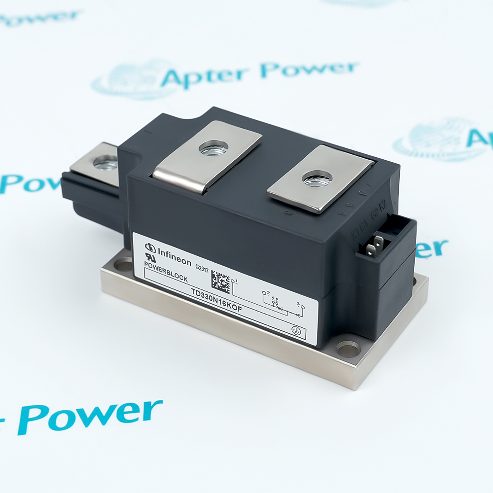
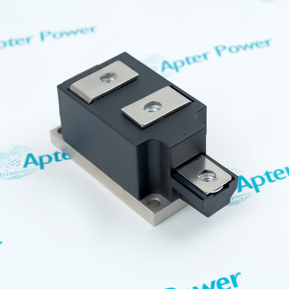
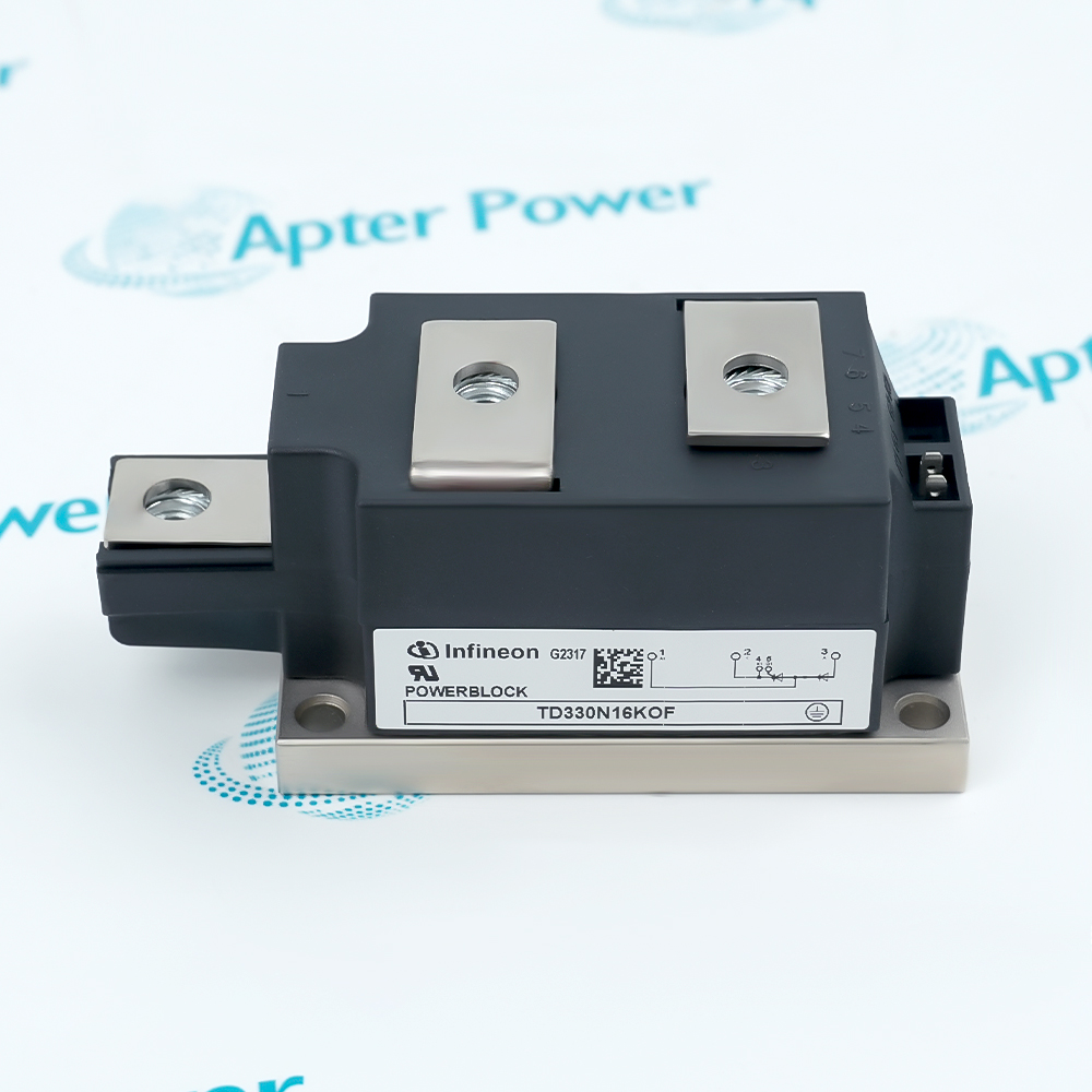
TD330N16KOF

Thyristor and Diode Power Semiconductor Module
Infineon TD330N16KOF
Product image is representative; revision or series may vary. Contact us to request a specific version.

Product Describe:

Infineon TD330N16KOF is a 1600 V thyristor/diode power module with a 330 A average-current rating at the specified case temperature.
  • Manufacturer part number
    TD330N16KOF
  • Shipping
    Swift global dispatch
  • Condition
    New, original product
  • Shipping size (est.)
    11.5cm x 5.0cm x 5.2cm
  • Country of Origin
    Germany
Get a quick price for TD330N16KOF
E-mail *
Mobile
Company
Content *
Quantity *
Upload (gif, jpg, jpeg, png, bmp, doc, docx, xls, xlsx, ppt, pdf, csv)
For more information on how your data is processed and stored by Apterpower please read our privacy policy

What happens after you enquire

  • 0

    Review your reference

    Send the complete Infineon TD330N16KOF reference, label photographs and required quantity.

  • 1

    Confirm the offer

    Review the offered revision, condition, included items and documents against the confirmed installation.

  • 2

    Arrange dispatch

    Confirm quantity, dispatch date, lead-time start and delivery details in the quotation.

  • Match the complete marking

    Provide the complete Infineon TD330N16KOF marking.

  • Check the offered item before ordering

    Request available label and connector photos. Have your maintenance team compare the offered TD330N16KOF with the installed equipment and applicable Infineon instructions.

Technical specifications for TD330N16KOF

  • Manufacturer:
    Infineon
  • Product Category:
    General Automation
  • Spare Part Number:
    TD330N16KOF
  • Weight:
    0.8 kg
  • Tariff Code:
    8537101190
  • Repetitive blocking-voltage class:
    1600 V
  • Average on-state current:
    330 A at case temperature 85 °C
  • Maximum RMS on-state current:
    520 A
  • 10 ms surge current at 25 °C:
    12500 A
  • 10 ms surge current at maximum junction temperature:
    10000 A
  • Maximum junction temperature:
    130 °C
  • Gate trigger current:
    200 mA maximum at 25 °C, VD = 12 V
  • Gate trigger voltage:
    2 V maximum at 25 °C, VD = 12 V
  • Maximum on-state voltage:
    1.28 V at 800 A and maximum junction temperature
  • Mounting torque:
    5 N·m, ±15%
  • Power-terminal torque:
    12 N·m, ±10%
  • Insulation test voltage:
    3.0 kV RMS for 1 minute

Information

Overview Downloads Applications / Compatibility Product Precautions
  • Infineon TD330N16KOF provides controlled and rectifying semiconductor paths for a power-conversion assembly whose cooling, gate drive and protection are engineered together.
Power conversion: Combine controlled and uncontrolled semiconductor paths in the selected converter topology.
Thermal design: Cooling and the load waveform determine the usable operating duty.
Protection coordination: Gate drive, surge withstand and fault protection must be assessed together.
The module combines thyristor and diode paths for the converter topology in which it is installed. The gate circuit controls the thyristor path, while the complete power circuit determines conduction duty.

Losses generated during operation must pass through the mounting interface to the cooling assembly. The thermal design must be evaluated with the actual current waveform and case conditions.

Equipment protection is coordinated with the semiconductor's permissible fault exposure. Short-duration surge capability and dielectric test results describe specific conditions, rather than additional continuous operating modes.
Controller platform reference: Infineon TD330N phase-control modules. Match the installed configuration and applicable instructions.
Infineon TD330N16KOF: original manufacturer technical information covering the specified interfaces and operating limits. Installation topics include: identify the power-circuit position, inspect the cooling interface, apply the correct mounting torque, check power-terminal connections, commission under controlled load.
Original manufacturer pages retain their technical context. Use the Apter Power guide with the applicable manufacturer instructions and approved installation design.
Prepare Infineon TD330N16KOF for its configured installation using these checks.
Isolate stored electrical energy

Follow the converter isolation procedure, including stored-energy discharge and verification. Identify all supply and control paths before touching the module; a stopped converter can still contain hazardous DC-link energy.

Review the actual duty

Compare current waveform, case temperature and expected losses with the module ratings. Do not size cooling from the 330 A figure alone or treat a short surge value as an allowable continuous load.

Restore the gate circuit

Check gate and cathode connections against the converter diagram. Inspect the drive components and lead routing, and verify that the circuit provides the intended trigger behavior without unintended noise-triggering paths.

Review protective coordination

Compare the fuse and protective-device characteristics with the appropriate surge and I²t conditions. Confirm that the design accounts for hot-junction operation and the actual prospective fault current.

Record the completed assembly

Retain the module identity, interface material, torque checks and test results. Return the converter to normal duty only after the power circuit, gate drive and cooling arrangement have been accepted together.

Commission under controlled load

Use the equipment's approved energization procedure and observe gate behavior, current sharing where applicable and thermal response. Investigate abnormal heating or conduction before increasing load.

Alternative Names

Infineon TD330N16KOF

Technical notes

Operating boundary: Do not treat surge current, insulation tests or gate thresholds as continuous operating setpoints.

Integration details: Match circuit topology, gate drive, cooling interface and protection coordination.


FAQ View All FAQ

  • Why is the surge-current rating of TD330N16KOF unsuitable for continuous-load selection?
    It applies to a specified short-duration event and initial thermal condition. Continuous duty must instead satisfy the current, loss and case-temperature limits of the actual converter waveform.
  • How does case temperature change the current assessment for TD330N16KOF?
    The average-current rating is associated with a stated case temperature. Ambient temperature alone does not establish that condition; evaluate the heatsink, interface and operating losses together.
  • Can the gate trigger specification of TD330N16KOF be used as the main-current rating?
    No. Gate trigger conditions describe how conduction is initiated, while the power path has separate current and thermal limits. Check both circuits in the converter design.
  • Why must mounting and power-terminal torques be distinguished on TD330N16KOF?
    They act on different mechanical interfaces and have different specified values. Interchanging them can compromise either thermal contact or electrical connection integrity.
  • Does the TD330N16KOF isolation test voltage define a permissible continuous operating voltage?
    No. A timed dielectric test is not a continuous circuit rating. Apply the appropriate blocking, insulation and installation limits to the actual equipment.
  • What should be checked before reusing thermal-interface material under TD330N16KOF?
    Confirm the intended interface arrangement and contact condition for this execution. Do not assume a pre-applied thermal material option is present simply because it is available in the product family.
  • Why does a hot TD330N16KOF require a different surge assessment from a cold device?
    The allowed surge condition depends on initial junction temperature. Coordinate protection against the applicable hot-state limit rather than relying only on the room-temperature figure.
  • How can abnormal heating after TD330N16KOF replacement be investigated?
    Review mounting contact, cooling, gate behavior and the actual current waveform under controlled load. A correct part marking does not rule out a connection or converter-duty problem.
SPEAK TO OUR TEAM
Let’s find the right solution for you.
Send us the part number, quantity and delivery destination. Our team will help confirm availability and lead time.
  • Whatsapp: +86 18030235313

    Send us a message.
  • sales13@apterpower.com

    Complete our online form.
  • +86 18030235313

    Speak to our team in your native language.