Speak to a sourcing specialist
sales13@apterpower.com
Get a quick price for CC-TDOB11
E-mail *
Mobile *
Company
Content *
Quantity *
Upload (gif, jpg, jpeg, png, bmp, doc, docx, xls, xlsx, ppt, pdf, csv)
For more information on how your data is processed and stored by Apterpower please read our privacy policy

What happens after you enquire

  • 1

    Requirement review

    We review the part number, quantity and delivery requirements and ask for any missing details.
  • 2

    Quotation and availability

    We confirm the proposed item, condition, availability, price and estimated lead time in the quotation.
  • 3

    Order confirmation and dispatch

    Once the quotation and purchasing details are agreed, your contact will coordinate the order and available dispatch information.

Technical specifications for CC-TDOB11

  • Manufacturer:
    Honeywell
  • Product Category:
    DCS Systems
  • Spare Part Number:
    51308373-175
  • Estimated shipping dimensions:
    14.5x12x5.2cm
  • Weight:
    0.16 kg
  • Tariff Code:
    8537101190
  • Counliy of origin:
    USA
  • Output channels:
    32
  • Output architecture:
    Bussed 24 Vdc
  • Companion module:
    CC-PDOB01
  • I/O type:
    Digital output
  • Module positions:
    Single
  • Redundancy:
    Yes
  • System:
    Series C

Information

Overview Manuals Common Applications Product Precautions
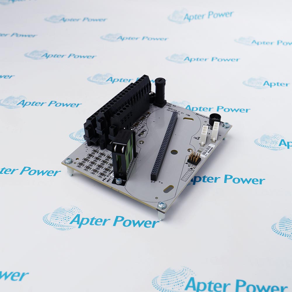
Honeywell CC-TDOB11 is a 32-channel bussed digital-output IOTA that routes Series C output commands and 24 Vdc field power to discrete loads.
  • Terminates thirty-two discrete output channels
  • Distributes the bussed field supply
  • Pairs with the CC-PDOB01 output module
  • Provides removable field connections

CC-TDOB11 operates with CC-PDOB01 Digital Output module, 24 Vdc field supply, Series C carrier, Protected field loads.

Its engineered use includes Solenoid-valve manifolds, Motor-starter command panels, Package-unit permissive outputs, Alarm annunciator drives.

Important Notice: Confirm the complete CC-TDOB11 marking, installed-system configuration, field connections and controlled functional test before commissioning or replacement.


Apter Power CC-TDOB11 Manuals and Guides
Apter Power CC-TDOB11 Product Technical Reference PDFHoneywell CC-TDOB11 Official Technical Manual PDF
The first document is an Apter Power model-specific technical reference. The second supports installation, configuration and engineering verification for CC-TDOB11.
Solenoid-valve manifoldsTerminates thirty-two discrete output channels
Motor-starter command panelsDistributes the bussed field supply
Package-unit permissive outputsPairs with the CC-PDOB01 output module
Alarm annunciator drivesProvides removable field connections
Read the applicable Honeywell instructions before work. Verify CC-TDOB11 and the installed Experion Series C I/O configuration.
1Verify the complete CC-TDOB11 marking and its assigned Experion Series C I/O position before work.
2Isolate the applicable power and field energy before disconnecting CC-TDOB11.
3Protect CC-TDOB11 connectors and electronic assemblies with approved ESD controls.
4Record the installed wiring, channel assignment and configuration before replacement.
5Match CC-PDOB01 Digital Output module and 24 Vdc field supply to the documented system arrangement.
6Commission CC-TDOB11 with controlled status, signal and diagnostic checks.
7Retain the final solenoid-valve manifolds functional-test result in the maintenance record.

Technical notes

Confirm the bussed 24 Vdc source, load polarity and channel fuse condition before inserting the companion output module.

FAQ View All FAQ

  • Does CC-TDOB11 match CC-PDOB01 Digital Output module in a Solenoid-valve manifolds installation?
    Verify the complete CC-TDOB11 marking, the documented Experion Series C I/O position and the installed CC-PDOB01 Digital Output module before fitting the assembly.
  • How should CC-TDOB11 be wired when it must terminates thirty-two discrete output channels?
    Isolate the circuit, identify every terminal and reproduce the approved polarity, shield and channel assignment for CC-TDOB11; then continuity-test the affected path.
  • Which Experion Series C I/O records should be captured before removing CC-TDOB11?
    Record the as-found wiring, installed position, active configuration and diagnostic state associated with CC-TDOB11 before disconnection.
  • What controlled test confirms that CC-TDOB11 can distributes the bussed field supply?
    Apply the approved field or simulated stimulus, observe the Experion Series C I/O indication and confirm the intended response without bypassing the normal interlocks.
  • Which 24 Vdc field supply condition should be checked when CC-TDOB11 reports an abnormal state?
    Check the 24 Vdc field supply supply, seating and connection first, then compare channel diagnostics with the recorded CC-TDOB11 baseline.
  • Can CC-TDOB11 be moved directly into Motor-starter command panels without validating Protected field loads?
    No. Confirm the Protected field loads, revision, connection scheme and Experion Series C I/O configuration before transferring CC-TDOB11 to that duty.
  • What maintenance evidence is required after CC-TDOB11 is used for Package-unit permissive outputs?
    Retain the nameplate record, corrective action, final diagnostics and a controlled package-unit permissive outputs functional-test result for CC-TDOB11.
  • How should CC-TDOB11 be returned to service in Alarm annunciator drives?
    Restore power under control, verify pairs with the cc-pdob01 output module, exercise the intended signal path and release CC-TDOB11 only after the Experion Series C I/O remains in its approved operating state.
Related reading

Related cases and sourcing guidance

View all case studies
SPEAK TO OUR TEAM
Let’s find the right solution for you.
Send us the part number, quantity and delivery destination. Our team will help confirm availability and lead time.
  • Whatsapp: +86 18030235313

    Send us a message.
  • sales13@apterpower.com

    Complete our online form.
  • +86 18030235313

    Speak to our team in your native language.