-
Match the complete marking
Retain 531X133PRUALG1 in full. Check connectors, jumper configuration and the installed drive engineering records.
-
Check the offered item before ordering
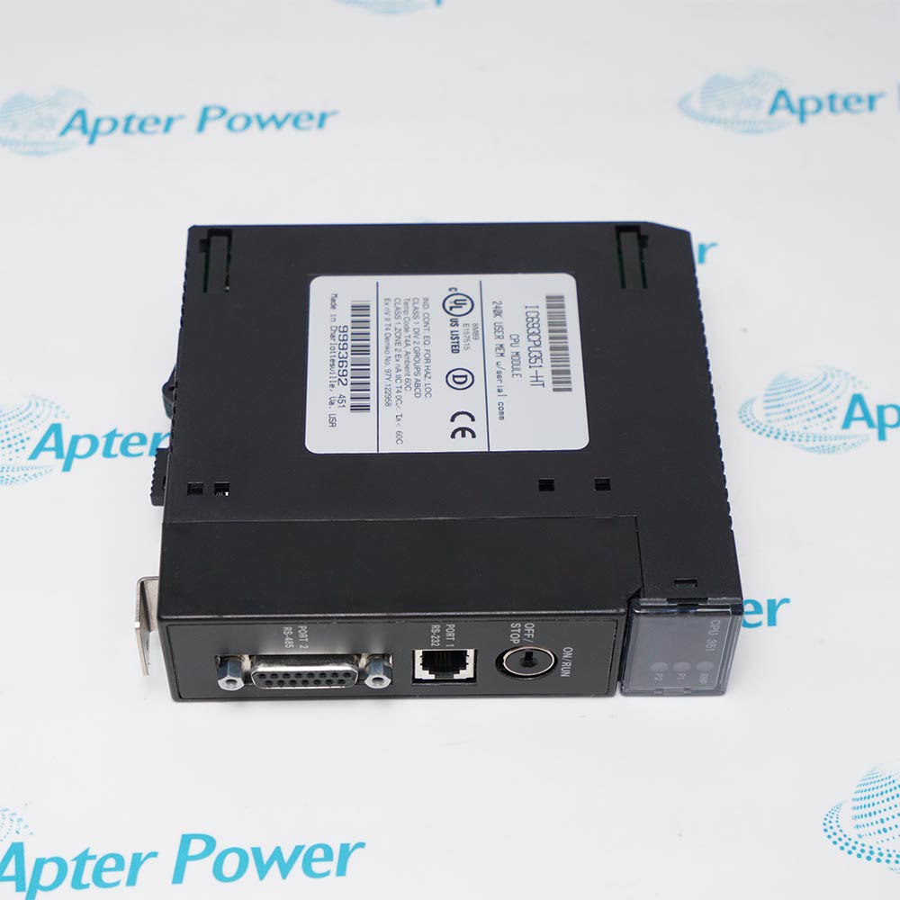
Request available label and connector photos. Have your maintenance team compare the offered 531X133PRUALG1 with the installed equipment and applicable GE documentation.
Technical specifications for 531X133PRUALG1
-
Manufacturer:General Electric
-
Product Category:General Automation
-
Spare Part Number:531X133PRUALG1
-
Weight:0.14 kg
-
Tariff Code:8537101190
-
Product type:Process interface board
-
Design family:531X133PRU
-
Analog tachometer adjustment:SW1 coarse selection; P1 TACH SCALE trim
-
Process follower adjustment:P4 PF GAIN and P5 PF OFF
-
Setpoint adjustment:P6 STP SCALE
-
Speed feedback zero:P7 SFB ZERO
-
Serial interface design:Jumper-configured RS-232C or RS-422
-
Speed meter output design:SMET analog output; unavailable with digital tachometer feedback
-
Digital tachometer design:Selectable doubling and quadrature processing
Information
- General Electric 531X133PRUALG1 supports PRU process-interface maintenance where drive signals must be matched to the installed tachometer, process transducer and communication arrangement.
Design family: 531X133PRU
Adjustment functions: Tachometer scaling, follower gain and offset, setpoint scaling
The PRU process-follower circuit uses P4 PF GAIN and P5 PF OFF to adjust gain and offset for 1-5, 4-20, 5-50 or 5-65 mA transducer inputs, with a conditioned reference up to 10 V at PFRF. JP2 and JP3 select the follower range. P6 STP SCALE adjusts the definable input at STPRF, whose function is established by the drive elementary drawings and engineering notes.
The PRU serial link provides jumper-selected RS-232C or RS-422 receive, transmit and handshake modes. Its analog speed-meter circuit is adjusted by P2 SMET for 10 V at maximum motor speed with a maximum load of 2 mA; this output is unavailable with digital tachometer feedback. Configuration and revision-dependent wiring must follow the installed drive drawings.
-
GE 531X133PRUALG1 technical reference
Prepared by Apter Power - PDF, 5 pages, 26.7 KB. PRU signal interfaces, adjustment functions and revision considerations. -
GE 531X133PRUALG1 installation planning guide
Prepared by Apter Power - PDF, 5 pages, 26.4 KB. Configuration review, replacement planning and functional acceptance.
Platform applications: The applications below describe PRU design functions. Verify the complete board revision and drive arrangement before replacement.
-
Analog speed feedback
Condition an analog tachometer signal using the coarse range selection and tachometer trim. Match AC or DC mode to the installed feedback source. -
Process follower input
Adjust the follower gain and offset for the connected process signal. Use the configured current-loop range and drive calibration procedure. -
Digital tachometer interface
Review the selected tachometer signal type, doubling and quadrature processing against the installed drive. Check return wiring when changing PRU revisions. -
Serial control interface
Use the documented RS-232C or RS-422 selections with matching receive, transmit and handshake settings. Confirm the drive-level communication arrangement.
Compare 531X133PRUALG1 with the installed board; a shared PRU family name does not prove a direct replacement.
Record switch, jumper and potentiometer settings before replacement. Apply the drive drawings and factory configuration for the installation.
Check the actual tachometer type. The analog SMET output is unavailable with digital tachometer feedback.
For revision changes, verify complementary input and PSPL return connections using the applicable GE procedure.
Check receive, transmit and handshake selections together. RS-232C and RS-422 configurations must agree with the connected equipment.
Confirm follower range, gain and offset against the connected transducer. Do not copy settings from another application.
Alternative Names
Technical notes
Signal relationship: The PRU design separates analog tachometer scaling, process-follower gain and offset, and setpoint scaling. Match each adjustment to the installed drive elementary drawings.
Revision control: Keep the complete 531X133PRUALG1 marking. Review tachometer input and return wiring before replacing a different PRU revision.
Technical reference: GE DC-300 Adjustable Speed Drives, GEK-85766B; GE 531X133PRUALG1 board identification.

FAQ View All FAQ
-
What does 531X133PRUALG1 do in the PRU interface design?It provides process and tachometer signal interfacing. The PRU design conditions follower and speed-feedback signals; it is a control interface board rather than a motor power stage.
-
How are analog tachometer scaling adjustments separated?SW1 selects the coarse analog tachometer range and AC or DC mode. P1 TACH SCALE provides the trim adjustment. The installed drive configuration determines the required settings.
-
What is the difference between PF GAIN and PF OFF?P4 PF GAIN adjusts the process-follower gain, while P5 PF OFF adjusts its offset. Current-loop selection and calibration must agree with the connected transducer and installed drive configuration.
-
Can the SMET output represent digital tachometer feedback?The PRU analog speed-meter output is not provided when the system uses digital tachometer feedback. For an analog tachometer arrangement, P2 SMET is the meter-output adjustment.
-
Is the PRU serial interface Ethernet?The documented serial interface uses jumper-selected RS-232C or RS-422 electrical signalling. These selections are not Ethernet interfaces; receiver, transmitter and handshake settings must agree.
-
What does P6 STP SCALE adjust?P6 adjusts the definable input associated with the STPRF test point. Its application is established by the drive elementary drawings and engineering notes, so the function is checked against the installed configuration.
-
What is P3 DVM TRIM used for?P3 calibrates the optional Programmer DVM indication. The PRU procedure uses the DVM test point connected to the +5 V reference and adjusts the display to 5.00.
-
Why must tachometer return wiring be reviewed during a PRU revision change?GE identifies a single-ended digital tachometer return-path change between AJ-and-earlier and AK-and-later PRU designs. A replacement review must check the actual board revision, complementary inputs and PSPL return arrangement; matching the PRU family alone does not establish interchangeability.
Supporting new and legacy automation
-
Please try to be as accurate as possible with your search.
-
We can quote you on 1000s of specialist parts, even if they are not listed on our website.
-
We can't find any results for “”.
You May Also Like
Product Browsing History
-
Whatsapp: +86 18030235313
Send us a message. -
sales13@apterpower.com
Complete our online form. -
+86 18030235313
Speak to our team in your native language.