
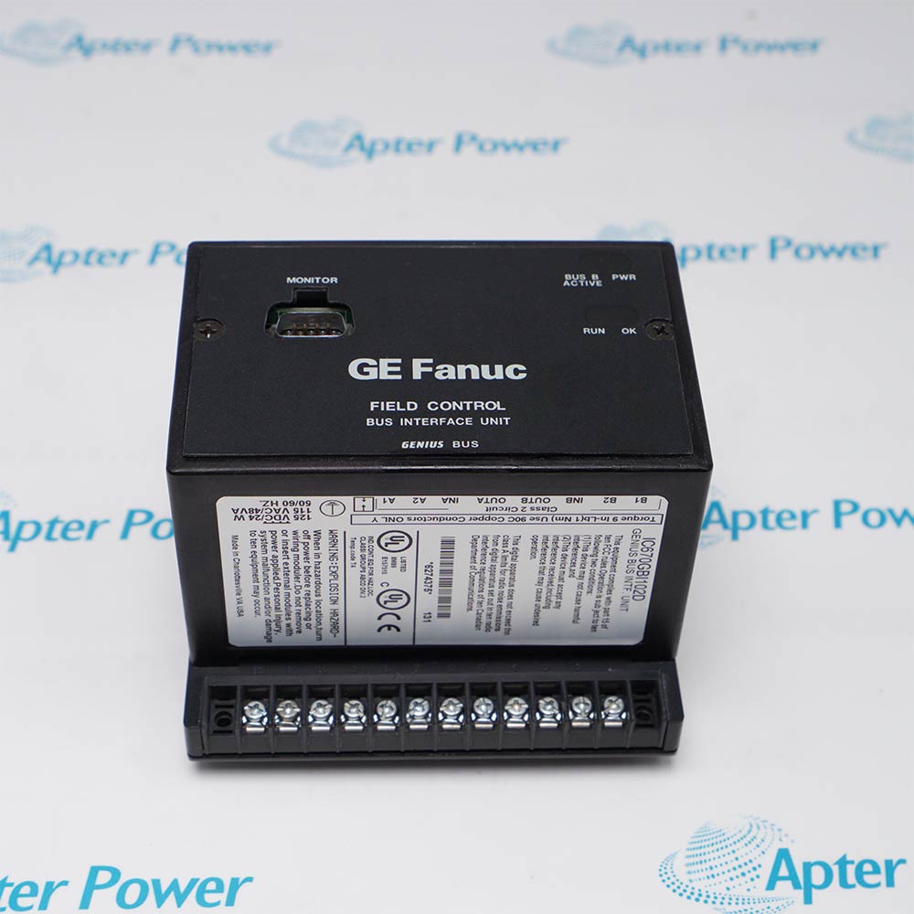

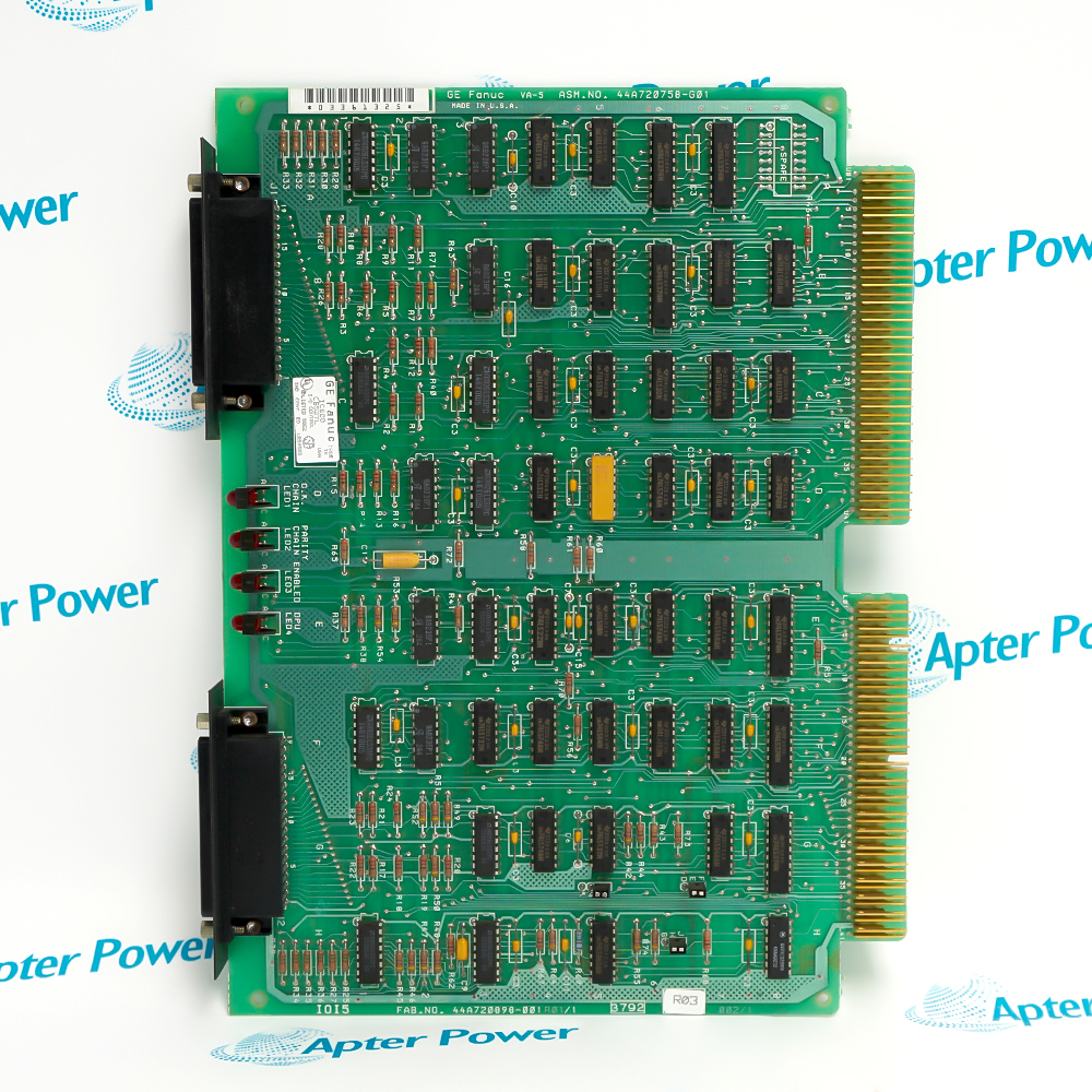

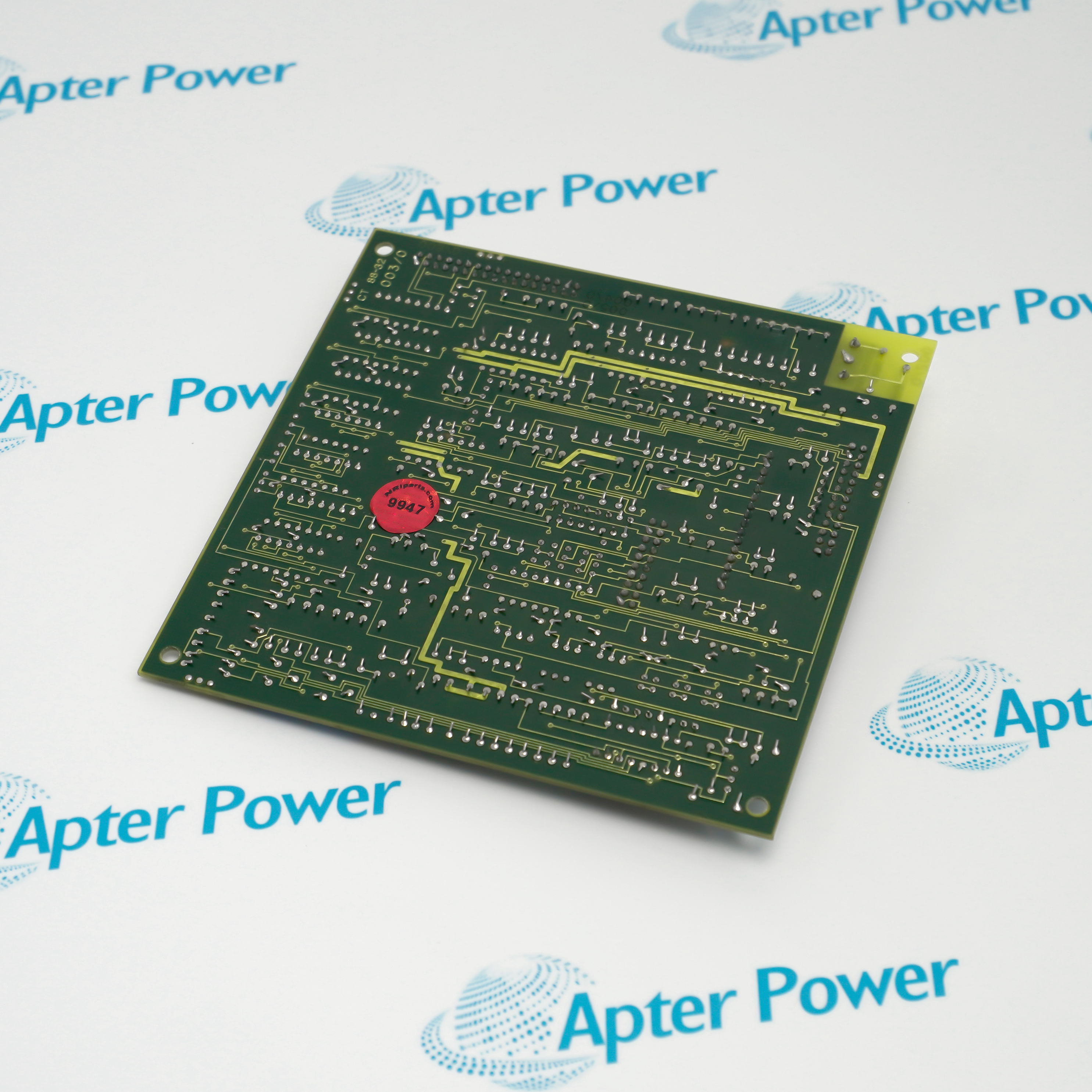
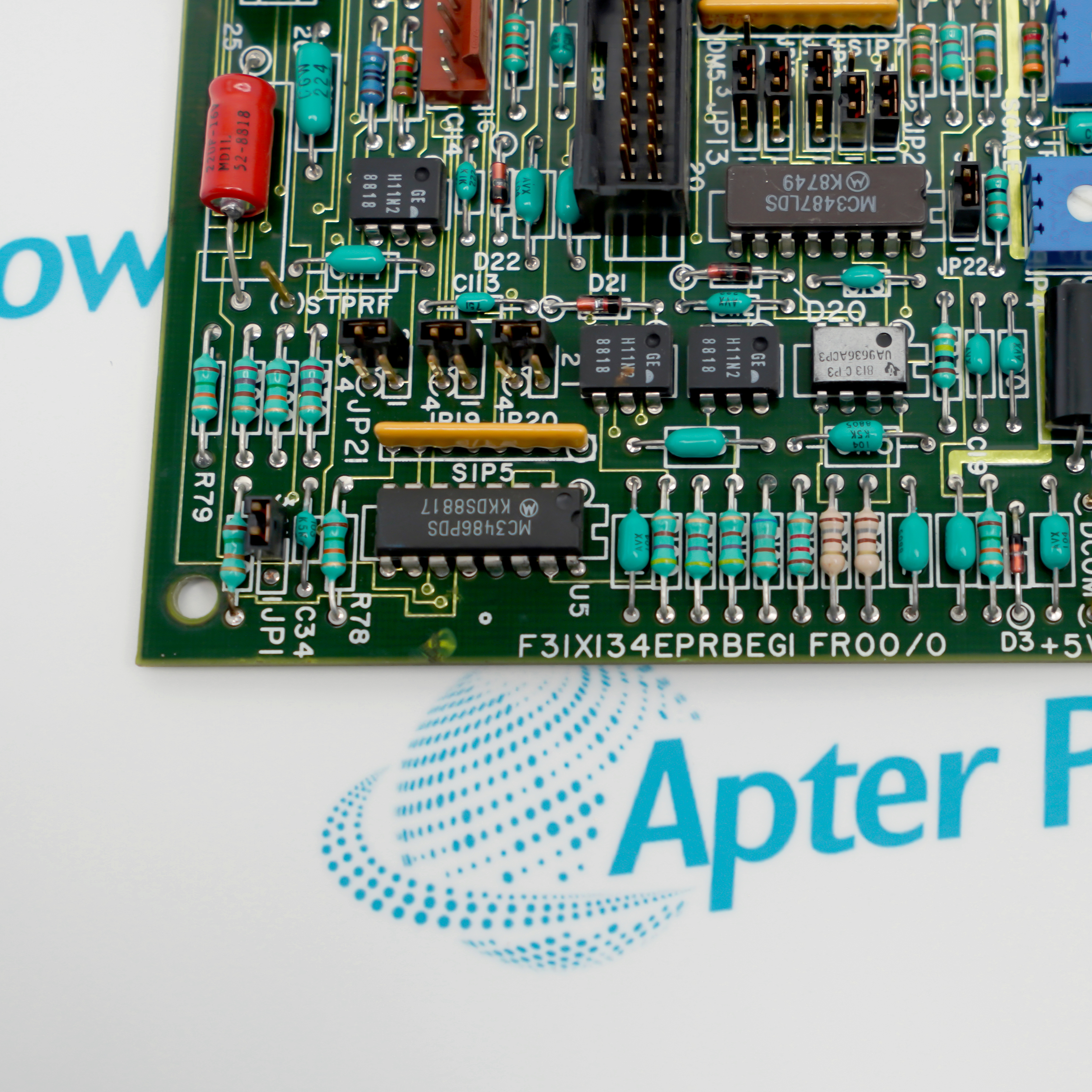











F31X134EPRBEG1-FR00-0 is installed with GE DC-300 drive, Installed encoder/process feedback wiring, Drive control-card assembly, Approved drive setup and maintenance record.
Engineered applications include DC motor speed feedback, Adjustable-speed drive restoration, Encoder-interface maintenance, Drive commissioning verification.
Important Notice: Isolate the DC-300 drive, record every connector and jumper, preserve encoder polarity and shielding, and verify feedback direction and drive response at controlled speed.
The first document presents model-specific technical identity and engineering data. The second provides a separate installation, connection and commissioning workflow.
F31X134EPRBEG1-FR00-0 supports this documented GE DC-300 adjustable-speed drive engineering task.
F31X134EPRBEG1-FR00-0 supports this documented GE DC-300 adjustable-speed drive engineering task.
F31X134EPRBEG1-FR00-0 supports this documented GE DC-300 adjustable-speed drive engineering task.
F31X134EPRBEG1-FR00-0 supports this documented GE DC-300 adjustable-speed drive engineering task.
Verify the complete F31X134EPRBEG1-FR00-0 marking and the assigned GE DC-300 adjustable-speed drive position before work.
Place the connected machine or process in the approved maintenance state before disturbing F31X134EPRBEG1-FR00-0.
Isolate the applicable power and field energy, then confirm a safe state before disconnecting F31X134EPRBEG1-FR00-0.
Record connector, conductor, slot and configuration identities before removal of F31X134EPRBEG1-FR00-0.
Use ESD controls and protect keyed interfaces, exposed contacts and electronic assemblies during handling.
Confirm that the installed companion hardware and approved project match the F31X134EPRBEG1-FR00-0 arrangement.
Restore power in a controlled sequence and review device, rack and host diagnostics.
Prove the intended function and retain the final test result before returning F31X134EPRBEG1-FR00-0 to service.



Copyright Notice © 2026 apterpower.com All rights reserved,Apter Power is not an authorised distributor or representative of the manufacturers featured on this website. Brand names and trademarks featured are the property of their respective owners.