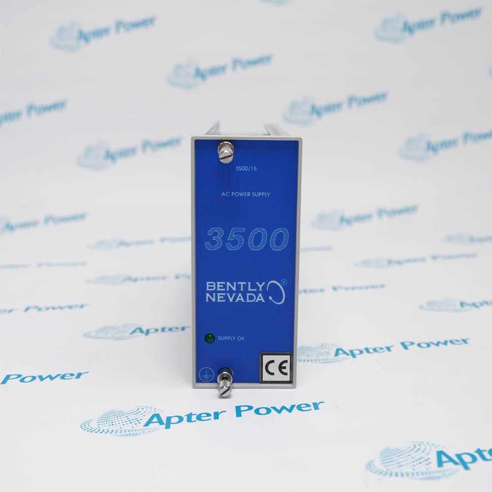
If your 3500/15 power supply replacement involves a legacy Bently Nevada 127610-01 AC Power Supply Module, do not order the 3500/15 106M1079-01 as a front-module-only swap. Bently Nevada's transition guidance identifies 106M1079-01 as the Universal AC replacement, but it must be paired with the 106M1081-01 Universal AC PIM. A new main module cannot be mixed with a legacy 125840-01 or 125840-02 PIM.
This guide treats the job as a power-position conversion rather than a search for a visually similar spare. It is written for electrical engineers, maintenance managers, and MRO buyers who must define the paired hardware, site input, redundancy plan, and acceptance criteria before an outage begins.
Which 3500/15 Parts Must Be Replaced Together?
When converting a legacy 127610-01 position to the Universal AC design, replace both the main module and rear PIM as a matched pair: 106M1079-01 with the 106M1081-01 Universal AC Power Input Module. The table below summarizes the decision.
| Question |
106M1079-01 |
127610-01 |
Approval rule |
| Is the number in the current OEM 3500/15 datasheet? |
Yes. It is the Universal AC Power Supply Module. |
No. A 2016 OEM update identifies it as the legacy AC module that was phased out. |
Use the OEM transition path, not visual similarity. |
| Is a matching rear module defined? |
Yes. Pair it with 106M1081-01 Universal AC PIM. |
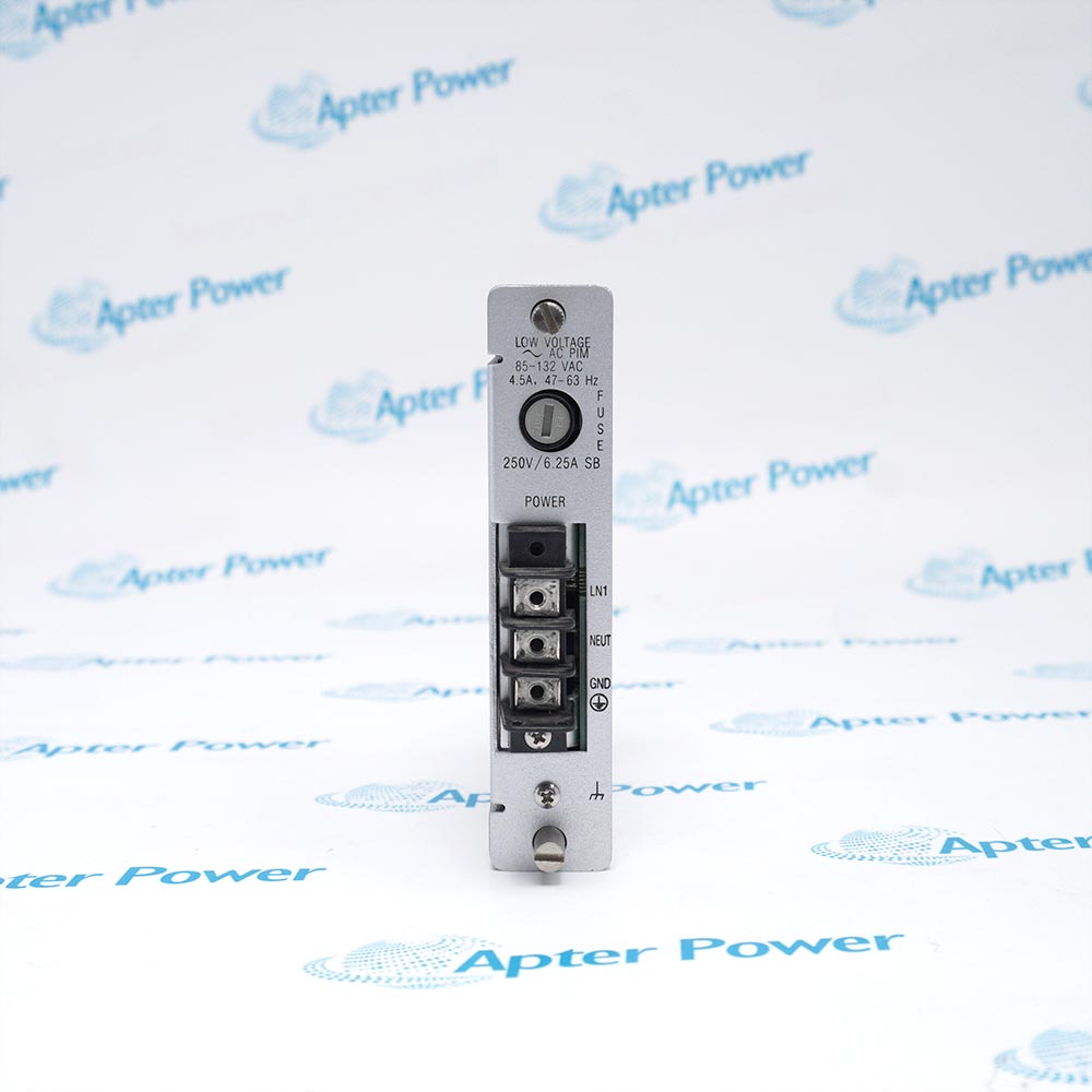
Yes. Legacy installations used 125840-01 high-voltage AC or 125840-02 low-voltage AC PIM. |
Record and verify the installed rear PIM separately. |
| Can the current Universal AC supply be mixed with legacy AC input hardware? |
No. |
No. |
Replace the main module and PIM as a matched generation set. |
| What else must match? |
Input type, top or bottom supply position, approvals, redundancy, and rack configuration record. |
The same, after identity is proven. |
Approve a complete front and rear pairing, not an isolated module number. |
The key procurement point is that 106M1079-01 is the current Universal AC replacement path, but it is not a front-module-only substitute for 127610-01. When the legacy part is no longer available, the OEM update requires paired replacement of the legacy main module and PIM with the Universal AC versions.
Why the Complete 3500/15 Part Number Matters
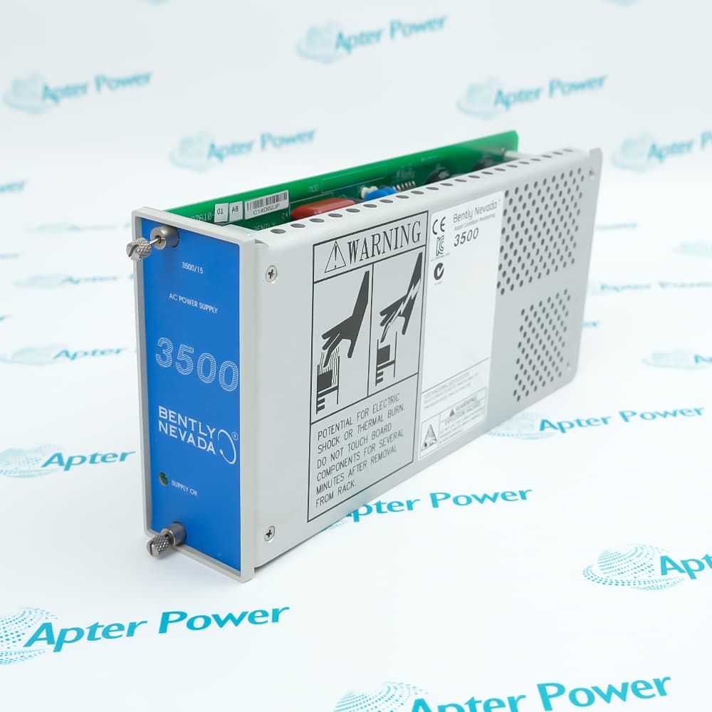
The 3500/15 is a half-height power-supply system installed in the designated left-side positions of a 3500 rack. A rack may use one supply or two. In a dual-supply rack, either supply is designed to power the full rack, with the lower unit acting as primary and the upper unit as backup.
That architecture creates several identifiers that must not be collapsed into one description:
- The front Power Supply Module part number.
- The rear Power Input Module part number.
- The supply type, such as Universal AC, High Voltage DC, or Low Voltage DC.
- The top or bottom position in the rack.
- The agency approval selection.
- The hardware generation and revision.
The 3500/15 AC and DC Power Supplies datasheet uses a rack ordering structure that distinguishes the top and bottom supply choices. A shortened requisition such as "3500/15 power supply" removes the information needed to confirm the intended position, input type, and complete installed pairing.
The purchase order, receiving inspection, and maintenance record should all preserve the complete part numbers. This is especially important when a site is trying to replace a failed unit quickly during a turbine, compressor, power-plant, water-treatment, or process-plant outage.
Read the Rack as Two Power Positions
The OEM transition documents identify both numbers, but they belong to different generations. The legacy 127610-01 AC main module was used with either a 125840-01 high-voltage AC PIM or a 125840-02 low-voltage AC PIM. The current 106M1079-01 Universal AC main module is paired with 106M1081-01.
For a like-for-like legacy spare, confirm that the physical label, revision, rear PIM, voltage version, site input, and approval requirement all agree. For a transition to 106M1079-01, quote the 106M1079-01 and 106M1081-01 as a matched set unless the Universal AC PIM is already verified in that same supply position.
Create a power-position record for the lower and upper rack positions before deciding what to buy. Each record should connect the front module to the rear PIM behind that same position.
| Record element |
What to capture |
| Position |
Lower primary, upper backup, or unoccupied. |
| Front supply identity |
Full part number, assembly, revision, serial number, and a readable label photo. |
| Rear input identity |
Full PIM number, terminal condition, and a photo showing the complete label. |
| Electrical source |
Nominal voltage, frequency, protective device, and controlled drawing reference. |
| Installed state |
Healthy, failed, intermittent, removed, or held as a spare. |
| Approval basis |
Required agency or hazardous-area approval for that rack location. |
Use unit-specific images for the proposed replacement as well. Catalog photography may show the product family, but it cannot prove the revision, serial identity, physical condition, or included rear module of the unit being offered.
Treat Each Front Module and Rear PIM as One Pair
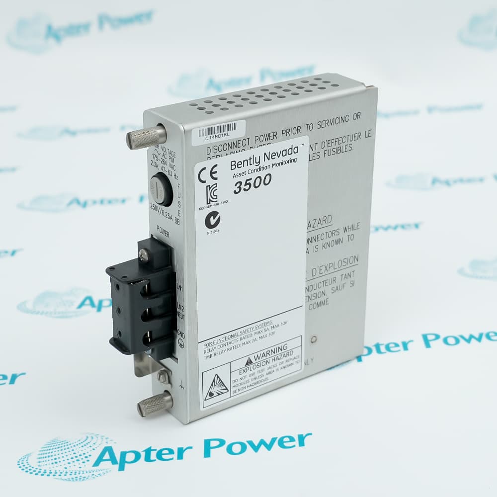
The front supply and rear PIM are different modules with different part numbers and functions. The front module converts and regulates power for the rack. The rear PIM accepts the site input and forms part of the electrical and mechanical interface.
For the current Universal AC design, the OEM datasheet identifies:
| Component |
Current part number |
What to verify |
| Universal AC Power Supply Module |
106M1079-01 |
Front label, revision, serial number, position, and condition. |
| Universal AC Power Input Module |
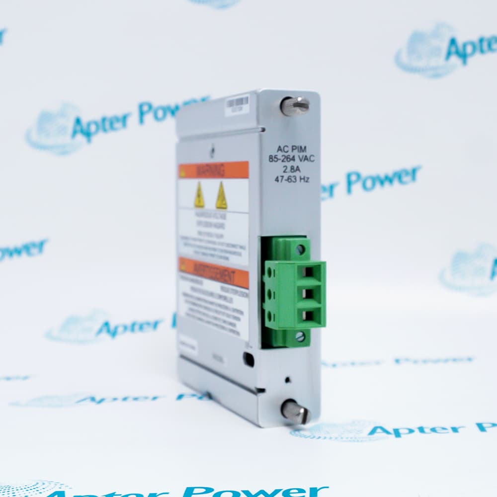
106M1081-01 |
Rear label, terminal condition, wiring basis, and agency requirement. |
This pairing should be recorded even if the rear PIM is not being purchased. A proposal to retain an unknown rear module should be treated as an unresolved compatibility question.
The quotation should state whether it includes the front supply only, the rear PIM only, or both. The phrase "complete power supply" is too ambiguous for a controlled purchase.
Use the OEM Generation Boundary
Generation is a compatibility requirement, not merely an age description. A 2016 Bently Nevada product update identifies 127610-01 as a phased-out legacy AC main module and 106M1079-01 as the new Universal AC module.
The current OEM datasheet states that the Universal AC supply and PIM are not compatible with the legacy 3500 AC supply and the legacy high-voltage or low-voltage AC PIM versions. It gives a similar warning for current and legacy DC supply and PIM generations.
This means a buyer should not create a hybrid assembly from a current front supply and an unidentified legacy rear PIM. Matching voltage words on two labels does not override the OEM generation warning.
Use this change-path matrix:
| Installed evidence |
Proposed replacement |
Decision |
| 106M1079-01 front with verified 106M1081-01 rear PIM |
Same current part and verified revision |
Continue with input, approval, condition, and test checks. |
| 127610-01 with 125840-01 or 125840-02 legacy PIM |
106M1079-01 front only |
Block. The new front module cannot be mixed with the legacy PIM. |
| 127610-01 with a verified legacy PIM |
106M1079-01 plus 106M1081-01 |
Valid OEM transition path, subject to input, approval, site procedure, and engineering checks. |
| One healthy supply in a dual-supply rack |
Replacement for the other position |
Continue only under the approved redundancy and maintenance procedure. |
| Unknown site input or approval requirement |
Any replacement |
Block until the electrical and regulatory requirements are confirmed. |
One useful distinction is often missed: a complete legacy AC main-module and PIM set may coexist in the same redundant rack with a complete Universal AC main-module and PIM set. The prohibited condition is mixing generations within one front and rear pair. This allows a staged rack transition, but each supply position must remain a correctly paired set.
Which Electrical Inputs Must Match the Installed Rack?
The supply type and site input must match the installed rack design. Current 3500/15 options include Universal AC, High Voltage DC, and Low Voltage DC. These are not interchangeable categories.
For 106M1079-01, the current OEM datasheet specifies a Universal AC input of 110 to 220 Vac nominal at 47 to 63 Hz. It also gives a wider accepted range that depends on installation classification: 85 to 264 Vac rms for nonhazardous locations and 85 to 250 Vac rms for hazardous locations.
Do not apply this full range to a legacy 127610-01 installation without first identifying whether its rear PIM is the former high-voltage or low-voltage AC version.
Before ordering, record:
| Electrical field |
Evidence source |
| Site nominal input and frequency |
Controlled electrical drawing and measured or verified site record. |
| Supply type |
Full front-module label. |
| Rear input-module type |
Full rear PIM label. |
| Protective device and conductor requirements |
Site drawing and applicable OEM installation manual. |
| Hazardous-area classification |
Site classification dossier and approval requirements. |
| Grounding arrangement |
Approved panel drawing and site standard. |
| Primary or backup position |
Rack layout and maintenance record. |
Do not use this article as a field-wiring procedure. Wiring, isolation, protective devices, and hazardous-area work must follow the applicable OEM manual, site electrical rules, and a qualified person's approved method.
Can One Supply Be Replaced in a Redundant Rack?
Yes, a 3500 rack with two correctly installed supplies is designed so either supply can power the entire rack, and the OEM states that removing or inserting one supply does not disrupt rack operation when the second supply is installed. However, this design feature is not a universal authorization for live work.
Before relying on redundancy, verify that:
- Two supplies are actually installed in the correct positions.
- The remaining supply is healthy and correctly rated for the complete rack load.
- The front and rear modules belong to compatible generations.
- The rack has no unresolved power or backplane faults.
- The site risk assessment permits the planned maintenance state.
- The OEM procedure and local electrical safety rules are available.
- Operations understands that redundancy will be temporarily reduced.
- A rollback and escalation plan is approved.
If any point is unknown, schedule a controlled outage or obtain qualified engineering direction. Do not use redundancy as a reason to bypass lockout/tagout controls, hazardous-area, arc-flash protection, or site permit requirements.
What Should Be Checked Before Power Is Restored?
Before power restoration or return to normal redundant operation, prove that the received equipment matches the approved scope and that the installation has not created a mixed-generation or miswired assembly.
Use this pre-power hold point:
- Match the delivered front and rear part numbers to the approved purchase order.
- Record serial number, revision, condition, and any supplier repair disclosure.
- Inspect connectors, terminals, fasteners, guides, and the rack backplane for damage or contamination.
- Confirm primary and backup positions against the controlled rack drawing.
- Confirm the site input, frequency, and approval requirements.
- Verify the rear PIM and front supply are an OEM-supported generation pair.
- Check conductor identification, grounding, protective devices, and terminal torque under the approved procedure.
- Confirm no tools, packaging, loose hardware, or foreign material remain in the rack.
- Document all pre-existing alarms or rack faults.
- Set clear stop conditions for unexpected status indications, odor, heat, noise, or abnormal current.
The person signing this hold point should have access to the applicable 3500/15 manual and the site's authorized electrical procedure.
Define the Electrical Acceptance Window
Function testing must show that the replacement delivers stable rack power under the site's approved operating plan. A lit faceplate is only one observation; it does not prove correct pairing, normal rack behavior, or usable redundancy.
Set the pass evidence and stop condition before energization:
| Checkpoint |
Evidence for acceptance |
Stop condition |
| Installed identity |
Front module, rear PIM, serial number, and rack position match the released work pack. |
Any unapproved part or position difference. |
| Initial power-up |
Expected Supply OK state with no abnormal sound, odor, heat, or electrical behavior. |
Unexpected indication or physical symptom. |
| Rack response |
Monitors, TDI, and rack communication return to the documented pre-work state. |
New power, communication, or module fault. |
| Normal load |
Rack remains stable for the site's defined observation period. |
Voltage instability, repeated event, or abnormal temperature rise. |
| Redundancy |
Each complete supply position supports the rack when the authorized test plan calls for proof. |
Transfer causes an unacceptable disturbance or the remaining supply is unhealthy. |
| Closeout |
Measurements, photos, events, exceptions, and approval are attached to the maintenance record. |
Missing evidence or an unresolved deviation. |
The detailed energization and transfer method must come from the applicable OEM manual and the site's electrical procedure. If a result falls outside the written acceptance window, stop the test and investigate it instead of redefining the expected result.
Build the Replacement as a Bill of Material
The commercial request should describe a complete power position. This lets us determine whether the request is for an exact legacy spare, a Universal AC conversion set, or one stage of a two-position migration.
Specify these line items and dependencies:
| Scope item |
Required purchasing detail |
| Rack position |
Lower primary or upper backup, plus the status of the other position. |
| Main module |
Installed number and requested number, including assembly and revision where available. |
| Rear PIM |
Installed number, whether it will be retained, and the required replacement number. |
| Electrical basis |
Nominal input, frequency, location classification, and required approvals. |
| Quantity and condition |
Number of matched sets and acceptable condition categories. |
| Receiving evidence |
Reserved-unit photos, serial identity, disclosed repair history, and available test record. |
| Commercial terms |
Destination, required date, packing, lead time, and applicable warranty terms. |
For a Universal AC conversion, identify 106M1079-01 and 106M1081-01 as separate bill-of-material lines. For a legacy replacement, state whether the installed PIM is 125840-01 or 125840-02; do not submit an undifferentiated request for a "3500/15 power supply."
Send us the two module labels, the rack position, the site input, and the destination country through our RFQ form. We can then confirm the supply scope, current availability of 3500 modules, offered condition, lead time, and the unit-specific records available for that quotation.
Use our 106M1079-01 listing for a Universal AC request or our 127610-01 listing when you need us to check legacy stock.
Our role is independent sourcing; we are not an authorized representative or distributor for Bently Nevada. Any Apter Power warranty will be stated in the quotation, and the manufacturer's warranty does not cover products supplied by us.
Do not upload restricted plant drawings or confidential electrical records to a public form. If detailed engineering files are needed after the scope is established, use your organization's approved transfer method.
Final Decision for a 127610-01 Migration
Treat the move from 127610-01 as an assembly change. The Universal AC path consists of a 106M1079-01 main module and a 106M1081-01 PIM in the same power position. Neither current component should be combined with a legacy 125840-01 or 125840-02 PIM arrangement.
A dual-supply rack may support a staged migration because one complete legacy pair can coexist with one complete Universal AC pair. Whether the work can occur without a rack outage is a separate site decision based on the health of the remaining supply, the OEM procedure, and the approved electrical safety plan.


 Videos
 News
News Applications











Leave Your Comment