Before replacing a Bently Nevada 3500/32 125712-01, preserve the output behavior, not only the module number.
The Alarm Drive Logic for each relay, its normal energized or de-energized state, the rear I/O terminal arrangement, and the receiving field circuit must remain aligned. A mismatch can operate the wrong annunciator, interlock, or shutdown input. Control engineers, electrical maintenance teams, commissioning personnel, and MRO buyers should prepare four records before approval: hardware identity, relay logic and states, point-to-point circuit mapping, and channel test results. Plant trip philosophy and setpoint changes remain outside this replacement scope.
What Role Does the 3500/32 Relay Module Perform?
The 3500/32 converts selected status information inside a 3500 rack into discrete relay-contact outputs for external systems. Depending on the approved site design, those contacts may feed an annunciator, DCS input, ESD input, interlock, or shutdown circuit.
The current OEM documentation describes the 3500/32M as a four-output relay module. Each output has its own Alarm Drive Logic, which can combine Alert, Danger, Not OK, and individual PPL inputs from monitor channels using AND and OR expressions. The logic is configured in the 3500 Rack Configuration Software. See the current Bently Nevada 3500/32M datasheet.
That function creates three distinct layers that must not be confused:
- Source condition: a monitor channel produces an Alert, Danger, Not OK, or PPL state.
- Alarm Drive Logic: the configured Boolean expression decides whether a relay command is true.
- Field result: the relay contacts change state and the connected external system interprets that change.
A replacement check must follow the signal through all three layers. Seeing a relay LED change does not prove that the correct terminal changed state or that the intended DCS or ESD point received it.
The Rack OK relay is a separate function. The 3500 System Datasheet locates that relay on the Transient Data Interface I/O module, describes it as normally energized, and limits it to general annunciation rather than automatic machinery shutdown. Do not treat Rack OK wiring as one of the four 3500/32 protection outputs, and do not use a Rack OK test as evidence that the configured 3500/32 relay paths work.
Which Details Identify 125712-01 Correctly?
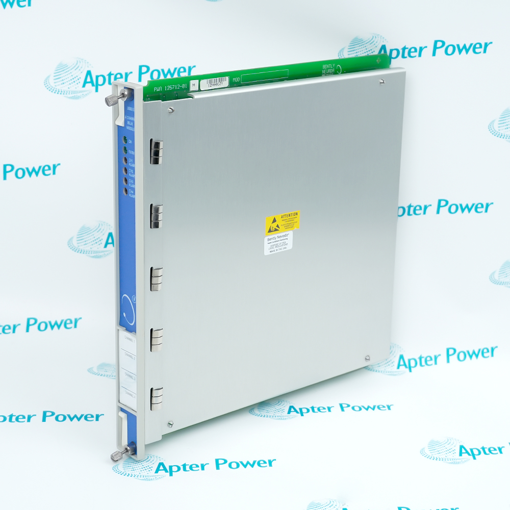
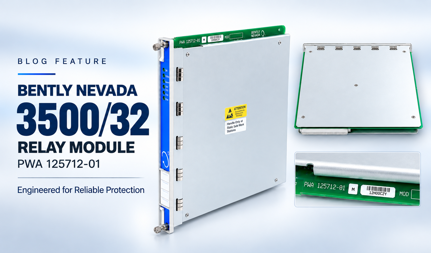
Part number 125712-01 identifies a legacy 3500/32 four-channel relay module in the installed base. Identification should begin with the physical label, but it cannot end there. A complete replacement requirement must connect the front module to its rear I/O hardware, rack position, configuration record, and approval basis.
Capture these fields from the installed equipment before issuing an RFQ:
The current OEM datasheet uses the model designation 3500/32M and lists 149986-02 as the spare four-channel relay control module. It separately lists 125720-01 as a spare four-channel relay output module available for repair only and 125720-02 as the output module for hazardous-area and functional-safety systems. Those current ordering entries do not, by themselves, prove that any one of those items is an unrestricted replacement for 125712-01 or for the rear I/O installed at a particular site.
Use the manual revision applicable to the installed rack. The OEM 3500 manuals index identifies document 129771 for the 3500/32 and 3500/32M four-channel relay modules and document 130432 for 3500 field wiring diagrams. If the physical labels, controlled drawings, configuration records, and applicable OEM documents do not agree, place the replacement on engineering hold. Do not resolve the difference by dropping a suffix or by choosing the nearest current catalog number.
How Is Alarm Drive Logic Documented Before a Swap?
Export or capture the installed Alarm Drive Logic before removing the module. A useful record must show more than a screenshot of a relay name. It should allow another qualified engineer to reconstruct why each output changes state.
Build one logic record per relay with the following fields:
Do not simplify (A AND B) OR C to a prose note such as “high vibration trip.” The shortened description removes the very structure that determines how the relay behaves. Also record any unused or forced input, active inhibit, maintenance override, or logic discrepancy as an exception. Do not silently correct it during a supposedly like-for-like replacement.
Map Each Relay to Its Field Circuit
After capturing the logic source, trace the output side. Use a point-to-point map that links the relay channel to the receiving system rather than a general note such as “goes to DCS.”
The completed map exposes common replacement risks: wires landed on the correct terminal number but the wrong relay channel, an undocumented interposing relay, a shared external supply, a stale receiving-system tag, or a rear I/O module whose contact arrangement differs from the drawing.
Record Energized and De-Energized States
“Normally open” and “normally closed” are not enough to describe the intended field behavior. The contact drawing may show the de-energized hardware state, while the process design may keep a relay energized during healthy operation. Power loss, a false logic result, and a true alarm demand can therefore produce different field interpretations.
Create a state-transition matrix before the swap. Fill it from the approved logic narrative, drawings, configuration, and controlled observations, not from assumptions.
This matrix answers the question that a wording-only comparison cannot: will the receiving circuit see the same state during normal operation, a commanded alarm, a reset, a detected fault, and loss of power?
What Wiring and Isolation Checks Are Required?
Relay output terminals can be connected to externally powered circuits even when the 3500 rack is de-energized. Before touching the rear I/O module or conductors, identify every source, obtain the required permit, apply the site's isolation and verification procedure, and prove the circuit state using approved test equipment.
The work pack should address:
- The exact rear I/O part number and terminal designation.
- Common, normally open, and normally closed conductor identification for each relay.
- External AC or DC source, return path, fuse, and isolation point for every circuit.
- Interposing relays, barriers, suppression components, shared commons, and other devices between the 3500 output and the receiving input.
- Wire numbers, ferrules, cable cores, shields, grounds, and spare conductors against the controlled drawing.
- The receiving DCS, ESD, PLC, annunciator, or trip-system point and the person responsible for its isolation.
- Required hazardous-area or functional-safety approvals and the exact contact-rating basis used by the site.
- Temporary jumpers, test links, bypasses, and their independent removal check.
Do not copy a voltage or contact-current value from a current 3500/32M datasheet into a legacy 125712-01 work order without confirming that the document, rear output module, approval option, load type, and installed application match. The current datasheet applies special restrictions to hazardous-area and functional-safety arrangements. The applicable manual and site engineering review must determine the permitted circuit values.
The system datasheet also distinguishes front modules from their corresponding rear I/O modules and states that I/O modules are not hot-swappable. No removal sequence is provided here. Follow the applicable OEM manual, the site's electrical-safety procedure, and the approved job plan for the exact rack configuration.
Stop the job if a wire identity is missing, two drawings disagree, an external source cannot be isolated, or the rear module label does not match the approved replacement basis. Photographs are helpful evidence, but they are not a substitute for verified wire and terminal identification.
How Should the Relay Outputs Be Function-Tested?
Test one relay path at a time under an approved commissioning procedure. The purpose is to demonstrate that the documented source condition produces the expected logic result, physical contact transition, and receiving-system indication. It is not necessary or appropriate for every maintenance test to operate a final shutdown device; that boundary must be defined by the asset owner before the test begins.
A disciplined sequence is:
- Verify the as-left configuration. Compare the installed file or captured settings with the approved baseline. Record the file identifier, revision, and reviewer.
- Confirm the test boundary. Identify whether the test ends at the relay contact, the DCS/ESD input, an annunciator, an interposing relay, or a controlled final-element test. Obtain operations approval for any simulated condition.
- Establish the normal state. Record the relay indication, measured contact state, and receiving-system status before applying a stimulus.
- Apply one approved source condition. Use the site's authorized simulation or test method for the specified Alert, Danger, Not OK, or PPL input. Do not create a real process hazard to prove a logic path.
- Observe the complete path. Confirm the logic result, relay indication, terminal contact transition, wire identity, and receiving point. Time correlation is important when several systems record the event.
- Verify reset or latch behavior. Remove the stimulus and confirm whether the output returns automatically or requires the approved reset action.
- Test fault and loss-of-power behavior where required. Use only an approved method and acceptance criterion. Do not infer fail-safe performance from the relay mode label.
- Restore and independently check. Remove all test forces, jumpers, bypasses, and inhibits; return the circuit to the approved state; and have a second qualified person verify restoration where site rules require it.
Record actual observations rather than “relay tested OK.” A useful channel record looks like this:
If the contact changes but the receiving point does not, keep the result open and troubleshoot the field circuit, interposing devices, power source, and receiving input. If the wrong relay changes, stop and compare the logic assignment, rack slot, and terminal map. A partial success must not be converted into full acceptance.
What Must Be Included in the Supplier Documentation?
The supplier package should answer a relay-specific question: which four-channel unit is being supplied, which rear I/O hardware is included, and what contact behavior was actually observed before shipment? It must not imply that a loose-module test proves the site's Alarm Drive Logic or field circuit.
Specify the required package as a set of linked deliverables:
The bench record should state its boundary plainly: observed contact operation is not proof of the installed Alarm Drive Logic, terminal wiring, external supply, receiving-system indication, or shutdown action. Those results belong in the site's channel test record.
For a useful RFQ, send us clear images of the installed 125712-01 front label and the rear output-module label, plus the rack slot, required approvals, quantity, destination country, and required-on-site date. If engineering review is requested, also provide the relay mapping and non-confidential configuration identifiers needed to compare the requirement. Do not send passwords or uncontrolled plant-sensitive files through an ordinary sales channel.
Use our 3500/32 125712-01 inquiry page to send the requirement. We will confirm the offered unit's availability, condition, included I/O, revision information, test scope, warranty, and shipping basis in the quotation.
You can also browse our Bently Nevada parts catalog or contact our team.
Relay-Path Acceptance Decision
Use one end-to-end trace for each of the four outputs:
source condition -> Alarm Drive Logic -> relay command -> energized/de-energized state -> rear contact -> field wire -> receiving-system point
Every step needs an as-found reference and an as-left result. A matching 125712-01 label does not preserve the configured expression. A correct expression does not prove the contact is landed on the intended circuit. A bench contact test does not demonstrate the DCS, ESD, annunciator, interlock, or shutdown input.
Approve the replacement only when the front and rear hardware identities agree with the engineering basis, each output follows the documented state matrix, and the observed receiving point matches the point-to-point map. Any broken link in that chain remains an open commissioning exception.


 Videos
 News
News Applications









Leave Your Comment