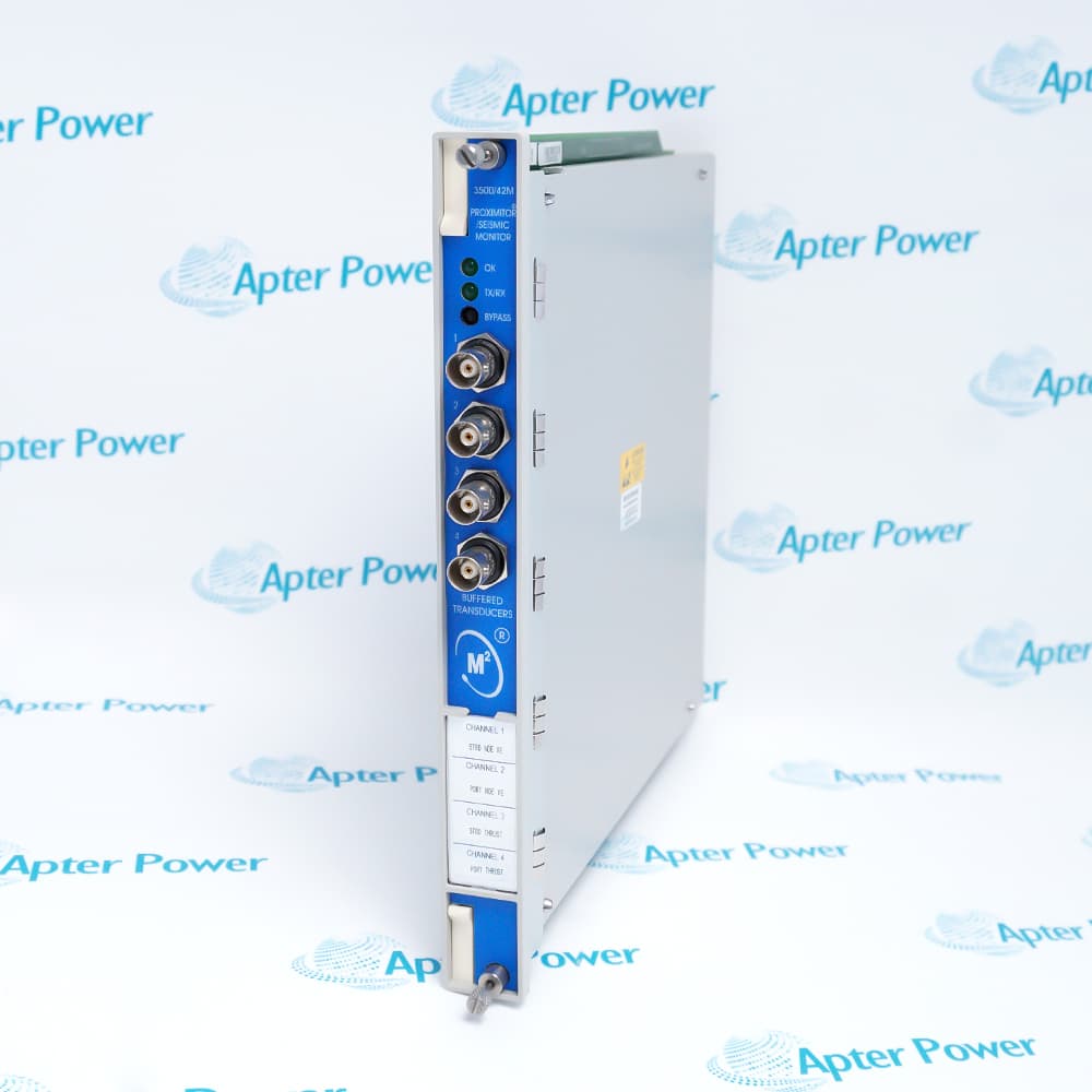
A complete replacement specification for Bently Nevada 3500/42M 176449-02 must cover the installed measurement chain, not only the front monitor card.
Record the rear I/O part number, termination and barrier arrangement, transducer family on each channel, Channels 1-2 and 3-4 functions, software or firmware baseline, and required validation checks. The rear I/O determines how field signals connect, while the rack configuration determines what the four channels measure. If either record is missing, a supplier can quote 176449-02, but the plant cannot confirm that the proposed unit fits its turbine, compressor, hydro unit, or pump application.
What Signals Can the 3500/42M Process?
The 3500/42M is a four-channel monitor that accepts proximity, velocity, or acceleration transducer signals. The configured channel type determines which vibration or position measurements the module produces and which alarm variables are available.
The current Baker Hughes 3500/42M datasheet lists the following programmable functions:
- Radial vibration
- REBAM
- Thrust position
- Acceleration
- Differential expansion
- Shaft absolute
- Eccentricity
- Circular acceptance region
- Velocity
Channels are configured in pairs. Channels 1 and 2 perform one function, while Channels 3 and 4 can perform the same function or a second function. That pairing rule belongs in the replacement specification because a four-channel list without its pair structure can conceal an incorrect assumption about the rear I/O or transducer mix.
Use the following distinction when documenting the installed application:
Do not use the list of supported functions as proof that every 176449-02 installation can be changed from one measurement type to another. The rear I/O hardware, connected transducers, firmware and software requirements, configuration, and approved machinery-protection design must support the selected function.
How Is 176449-02 Paired With the Correct I/O Module?
Identify the installed rear I/O module by its physical label and match it to the transducer and termination arrangement. Do not derive the rear part number from 176449-02 alone.
The current OEM datasheet lists 176449-02 as the spare 3500/42M Proximitor Seismic Monitor and gives the following I/O choices. This table is a specification map, not a statement that every option is interchangeable or currently available for every approval and installed revision.
The installed rear module may be more important to the buying decision than an attractive listing for the front card. A quote for 176449-02 should therefore state whether it covers the front module only or includes any rear I/O, connector, shunt, external termination block, or cable.
Identify Internal and External Termination Options
Internal termination and external termination are different wiring architectures. An internal-termination I/O accepts the field wiring at the rear rack module. An external-termination arrangement uses a separate termination block and a dedicated cable between that block and the rack I/O.
The OEM datasheet states that external termination blocks cannot be used with internal-termination I/O modules. It also instructs buyers to order the external termination blocks and cables separately when selecting an external-termination I/O. Record these items individually:
- Rear I/O part number and ordering option.
- Internal or external termination.
- External termination block part number, if used.
- Cable part number, length, connector type, and installed route, if used.
- Connector headers or shunts required by the installed arrangement.
- Field terminal numbers, channel assignments, and drawing revision.
Do not convert an installation from internal to external termination as an informal purchasing substitution. That is an engineered wiring change and may affect drawings, cabinet layout, cable routing, testing, spares, and approvals.
Identify Barrier and Shaft-Absolute Configurations
Internal-barrier and Shaft Absolute arrangements require their exact rear I/O identity and approved configuration evidence. They are not suffix details that can be inferred from the front card.
For internal barriers, capture which of the three 135489 variants is installed and how its transducer types are allocated across Channels 1 through 4. For a Shaft Absolute application, capture the 138708-01 or 138700-01 label, termination style, channel grouping, input sources, and the firmware and software baseline used by the approved system.
The current datasheet identifies additional firmware and software requirements for Shaft Absolute, internal-barrier, REBAM, Acceleration II, Velocity II, and circular-acceptance-region functions. Treat those requirements as configuration-specific. Verify them against the installed rack, the applicable OEM document revision, and the site's controlled software records rather than assuming that one current version statement applies to every legacy installation.
Which Channel Configuration Must Be Preserved?
Preserve a two-part channel-configuration record: one for Channels 1 and 2 and another for Channels 3 and 4. Each record must connect the physical transducers to the configured function and the values used by operations or protection.
Use a table like this before removing the existing module:
The current datasheet explains that each active static value can have an Alert setpoint and that Danger setpoints can be assigned to two active static values per channel. This does not define the correct setpoints for a specific machine. Preserve the site's approved values and engineering basis; do not copy settings from another bearing, machine train, or spare configuration.
Record the configuration file name, revision, date, rack identifier, slot, and reviewer. Screenshots are useful for a quick comparison, but the controlled export and approval history remain the primary restoration evidence.
What Should Be Checked in the Sensor Signal Chain?
Trace each input from the machine to the configured channel. A monitor-card replacement can expose a pre-existing sensor, cabling, grounding, or interface problem, so the acceptance record should separate the condition of the new card from the condition of the field signal chain.
A proximity-measurement path may include a probe, extension cable, Proximitor sensor, field cable, terminal or barrier, rear I/O, and the configured monitor channel. A seismic path may include a velocity or acceleration transducer, its power or interface arrangement, field cable, termination hardware, rear I/O, and the configured channel. Shaft Absolute and other specialized arrangements need the exact input grouping shown in the approved system records.
Build one line per channel:
For each channel, investigate discrepancies before blaming the front module. A Not OK state, unstable bias or gap, clipped waveform, unexpected polarity, excessive noise, or implausible static value can originate in the sensor, extension cable, Proximitor or seismic interface, field wiring, termination, I/O module, rack connection, configuration, or monitor card.
Individual probe, extension-cable, and Proximitor ordering codes remain outside this scope. Verify those components as a complete transducer system using their own OEM ordering documentation. The purpose here is to prove which signal chain the 176449-02 replacement must receive.
How Should the Replacement Be Validated?
Validate the replacement as a measurement-path restoration, with one result set for each of the four channels. A healthy front-panel LED is only one observation; it does not prove the correct I/O pairing, scaling, phase reference, processed values, or external data path.
Use the site's approved procedure and the applicable Bently Nevada user guide. The OEM 3500 manuals index identifies document 143489 as the 3500/42M Monitor User Guide. The current 3500 System Datasheet explains that the rack configuration includes alarm setpoints, channel names, relay logic, and signal-processing options. The replacement record should therefore compare both hardware and configuration.
A practical validation sequence is:
- Confirm the installed hardware path. Record the front-module label, rear I/O label, slot, termination arrangement, barriers, connectors, and channel terminal assignments.
- Compare the as-left configuration. Verify both channel pairs against the approved baseline, including function, range, units, filters, static values, alarm variables, setpoints, delays, and phase-reference assignments where applicable.
- Review module and channel status. Check the module OK, communications, bypass, and individual channel states under the approved operating condition.
- Compare transducer operating evidence. Record the applicable bias, gap, static value, or sensor status and compare it with the as-found baseline and engineering acceptance limits.
- Verify the dynamic measurement path. Using an approved test method, confirm the expected amplitude, frequency, phase, polarity, or processed output for the configured channel type. The test values and tolerances must come from the site procedure and applicable OEM documentation.
- Check alarm processing where required. Apply only an authorized simulation or test input, observe the configured Alert or Danger behavior, and document the result without changing plant setpoints to make the test pass.
- Compare external data. Where the rack feeds System 1, a display, DCS, historian, or other system, compare channel identity, units, value, status, and timestamp at the receiving destination.
- Close every temporary condition. Remove test inputs, forces, bypasses, temporary grounds, and jumpers; restore the approved operating state; and record exceptions and retests.
Use a measurement-focused result sheet rather than a generic “module tested” statement:
This validation boundary is deliberately different from a relay-output proof test. The 3500/42M record establishes that the intended transducer signals are acquired, processed, alarmed, and transmitted as configured. Any downstream shutdown or final-element test remains governed by the site's separate protection-test procedure.
What Information Produces a Faster, Cleaner Quote?
A precise RFQ should describe one installed measurement architecture. Send the front and rear labels together, then add the two channel-pair records and the required commercial terms.
Use this format:
Attach clear photographs of the 176449-02 front label, the complete rear I/O label, connectors, terminal area, and any external termination block. If the site permits sharing it, include a redacted channel summary or configuration screenshot that shows the two channel-pair functions without exposing passwords or sensitive plant data.
Our 3500/42M 176449-02 inquiry page provides the exact-model quote form. Our 3500 technical resources also show the commonly referenced 3500/42M-09-00 arrangement with 176449-02 and 140471-01. Treat that entry as a documented starting point, not proof that 140471-01 is correct for every 176449-02 installation.
We will confirm the offered unit, current availability, condition, included hardware, actual-unit evidence, test scope, warranty, and dispatch basis in the quotation. Suitability remains conditional until the installed I/O, transducers, configuration, approvals, and OEM records agree.
The Complete 176449-02 Specification
Write the replacement requirement as one complete specification:
176449-02 front module + rear I/O part number + termination/barrier arrangement + Channels 1-2 function + Channels 3-4 function + four sensor paths + configuration baseline + measurement-path acceptance record
If any term is unknown, mark it as an open engineering item instead of replacing it with a guess. The result is a cleaner RFQ, a defensible I/O pairing decision, and a validation plan that tests the signals the module is actually expected to process.


 Videos
 News
News Applications










Leave Your Comment