Bently NevadaŌĆÖs 3500 machinery protection system has become a quiet backbone of power reliability in turbine halls, generator rooms, and balance-of-plant systems worldwide. Baker Hughes reports more than 80,000 3500 systems deployed globally and roughly 5,000 new systems added each year, and they explicitly state that the 3500 is not obsolete and remains fully supported. For plants that depend on UPS-backed controls, inverters, and high-availability power supply systems, a neglected 3500 rack is not just an instrumentation issue; it is a direct risk to uptime and protection.
This guide distills maintenance best practices and troubleshooting procedures from Bently Nevada guidance, ABB rack documentation, training-oriented technical material, and field-oriented advice from service providers such as Ubest Automation and Reliability Controls. The focus is practical: what you should actually do to keep a 3500 healthy, trustworthy, and aligned with your overall power protection strategy.
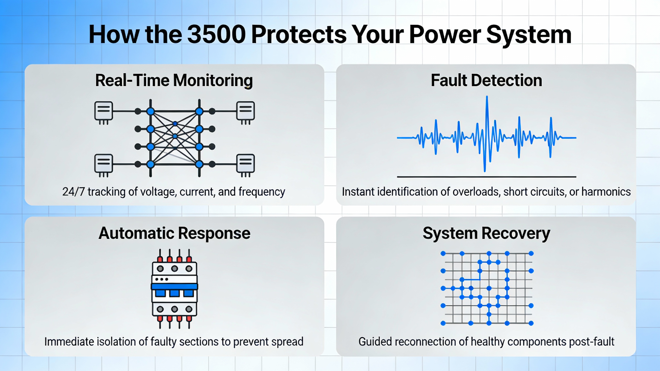
1. How the 3500 Protects Your Power System
The 3500 is a modular, rack-based machinery protection and condition-monitoring platform. Monitor modules accept inputs from proximity probes and seismic sensors, calculate vibration and position measurements, compare them against configured alarm setpoints, and drive relay logic that protects critical rotating equipment such as steam and gas turbines, generators, compressors, and large pumps.
Baker Hughes describes several key monitor types within the 3500 family. The 3500/40M Proximitor Monitor supports turbine supervisory measurements such as radial vibration, thrust position, differential expansion, and eccentricity, and it is widely used on steam turbines. The 3500/42M Proximitor/Seismic Monitor offers four programmable channels that can measure radial vibration, thrust position, acceleration, velocity, shaft absolute vibration, and related parameters. For aeroderivative gas turbines, the 3500/44M monitor integrates with Velomitor and accelerometer sensors and provides tracking filters for vibration at running speed. Hydro units use the 3500/46M Hydro Monitor, which handles signals from Proximitors, seismic sensors, dynamic pressure probes, and air gap sensors, and supports specialized measurements such as hydro air gap and hydro thrust.
The system as a whole is certified up to Safety Integrity Level 2 and is approved for hazardous area use when applied correctly. It also integrates with Bently NevadaŌĆÖs System 1 software for diagnostics and condition-based maintenance. Training materials for 3500 operation and maintenance consistently emphasize the distinction between protection and condition monitoring: the same hardware both initiates machine trips when danger thresholds are exceeded and provides trend data for reliability and asset management.
From a power systems perspective, this means that a single 3500 rack may stand between a vibration problem and an emergency trip of a turbine-generator that feeds an entire switchboard, UPS input, or critical process line. With about 80,000 units in service and approximately 5,000 new racks added each year, roughly one in fifteen deployed systems is newly installed each year, which underscores that the platform is still actively deployed and worth maintaining for the long term.
2. Architecture You Are Really Maintaining
To maintain a 3500 effectively, it helps to see what you are actually caring for: not just individual cards, but an architecture that ties sensors, protection logic, and communications into a single safety-critical path.
2.1 Rack, Power Supplies, and TMR Relay Path
ABB documentation for the 3500 rack highlights several structural elements that maintenance teams must treat as protection hardware, not generic I/O.
The rack itself houses a backplane, monitor modules, relay cards, and power supplies. Dual 3500 power supplies independently provide redundant power to the rack. In Triple Modular Redundant (TMR) configurations, a 3500/34 TMR Relay Module pairs two half-height monitors with one full-size I/O module. The two monitor cards are identically configured and process alarm information redundantly from the measurement modules, while the I/O card contains triplicate relays and control logic implementing two-out-of-three voting.
In practice, that TMR path is the last line of defense between high vibration and a trip relay that de-energizes your turbine or drive train. Maintenance on these elements is not cosmetic. Routine checks of supply health, relay self-check indicators, and configuration consistency across redundant monitors are required if you want the SIL 2 protection that the hardware is certified to provide.
Training material on 3500 operations stresses that alert and danger setpoints feed this relay logic, and that alarms may be latching or non-latching. During maintenance, verifying that these setpoints and relay behaviors still match current turbine and generator trip philosophies is just as critical as checking that a particular moduleŌĆÖs LEDs are green.
2.2 Intrinsic Safety and the Internal Barrier System
In hazardous surface-area installations, Bently Nevada offers 3500 I/O modules with integrated zener barriers. ABBŌĆÖs description of the 3500 Internal Barrier System explains how these barrier I/O modules, when used together with a 3500/04-01 Earthing Module, form an intrinsically safe system for vibration and process variable monitoring.
Several details from that documentation translate directly into maintenance tasks.
There must be exactly one earthing module per rack, and it occupies a rack slot. Part of periodic maintenance is confirming that this module is still in place, correctly wired, and providing intrinsic safety earth connections.
When an internal barrier system is used, the grounding of the 3500/15 power supply must be changed from its factory default setting. If someone replaces a supply and leaves the new unit at the default, that violates the certified grounding scheme, so configuration checks after power module replacement are essential.
RS-232 connections for rack interface modules, communication gateways, or a 3500/95 PC display must be isolated. The 3500/94 VGA display cannot be used in internal barrier systems. RS-422 and RS-485 connections remain allowed for specific modules such as the 3500/20, 3500/90, 3500/92, 3500/93, and 3500/95, but bussed transducers are not permitted with internal barrier I/O modules.
The earthing module supports two intrinsic safety earth connections for field cables with cross-sectional areas up to roughly 0.02 square inches, and it allows online testing of IS earth continuity. That design is an invitation to include IS earth checks in your live maintenance routines instead of waiting for a long outage.
Physically, internal barrier I/O modules force safe-area and hazardous-area wiring to remain separated by at least about 2 inches inside the module. Connectors are color-coded, green for safe and blue for hazardous, and use different pitches with quick-connect hardware. During inspections, those mechanical aids should be verified, not just taken for granted. If you ever find a workaround that defeats that 2ŌĆæinch separation or misuses the connectors, you are looking at a compliance and safety issue, not just an aesthetic problem.
2.3 Key Modules That Drive Maintenance Effort
Different modules drive different maintenance priorities, and vendor material helps make that clear.
Monitor modules such as the 3500/40M, 42M, 44M, and 46M carry the burden of vibration and position measurements. They are configured using the 3500 Rack Configuration Software, where each channelŌĆÖs measurement type, alarm setpoints, and filtering are defined. Their health is assessed not only through LEDs, but through comparison of live process data to expected baselines.
The 3500/22M Transient Data Interface (TDI) is the data gateway that Ubest Automation emphasizes as central to condition monitoring strategies. It captures high-resolution vibration and process data for diagnostics and forwards it to DCS, System 1, and historians.
Keyphasor modules provide the once-per-revolution speed and phase reference needed for synchronous vibration analysis. Proximitor and seismic monitor modules condition signals from proximity probes and seismic sensors; relay modules implement alarm and trip logic; communication gateway modules interface the rack to external control systems. A supplemental maintenance manual for PWPS and TP&M implementations of the 3500 documents fifteen distinct rack configurations and associated software templates for different turbine and mechanical-drive systems, making clear that each machine type has its own precise configuration.
Reliability Controls maintains a central repository of operation and maintenance manuals for these modules, including a general ŌĆ£All MonitorsŌĆØ manual, a System Rack Manual, multiple vibration, position, and temperature monitor guides, reciprocating machinery monitors, and communication and display manuals. The implicit guidance is straightforward: maintenance and operations personnel should always select the documentation, configuration template, and procedures that match the exact 3500 module and machine variant installed, rather than assuming that any ŌĆ£similarŌĆØ module or rack layout will behave the same way.

3. Building a Structured Maintenance Program
Vendor training material and field-oriented articles are consistent on one point: the 3500 is not a set-and-forget system. Structured operations and maintenance practices are essential to avoid both nuisance trips and dangerous missed trips.
3.1 Visual and Environmental Inspections
Ubest AutomationŌĆÖs detailed guide to the 3500/22M TDI begins with simple but often neglected tasks: visual and environmental inspections. Periodically, technicians should confirm that the 3500 rack and TDI module are clean, free from dust, oil residue, and condensation, and that each module is fully seated and locked in its slot. Wiring and connectors should be inspected for looseness, oxidation, or physical damage, since such defects frequently introduce noise and intermittent faults.
The same article emphasizes operating the rack within the manufacturerŌĆÖs temperature and humidity specifications, noting that excessive heat in industrial environments significantly shortens the life of electronics. For plants with UPS rooms and inverter cabinets that run warm by design, that point directly links 3500 maintenance with general power-room HVAC performance.
3.2 Configuration and Data Integrity Reviews
Configuration drift is a subtle threat. It arises from machine modifications, firmware changes, and ad hoc adjustments to alarm thresholds or channel assignments made under time pressure. UbestŌĆÖs guidance for the 3500/22M recommends regular reviews of machine train configurations, channel assignments, transducer mappings, alarm settings, and filters against current engineering specifications.
Operation and maintenance training materials for the 3500 echo this, recommending documented management-of-change procedures for any logic or setpoint modifications. They also stress the importance of periodically validating that historian and System 1 connections are capturing transient data without gaps or format errors, because long-term trending is only as good as the data you actually retain.
One real-world case from UbestŌĆÖs TDI article illustrates the cost of neglecting such checks. A power generation facility experienced intermittent, unexplained trips on a critical steam turbine. Vibration alarms did not match process conditions. Review of long-term trend data from the 3500/22M revealed a slow, months-long drift in the bias voltage of a key proximity probe. That drift gradually moved normal noise into the alert region. Implementing quarterly bias-voltage validation and replacing the failing probe during a scheduled outage eliminated the false trips and restored confidence in the protection system.
3.3 Firmware, Software, and Configuration Tools
Firmware and software are now part of the protection chain. The 3500/22M relies on internal firmware, communication drivers, and configuration tools running on engineering workstations. Ubest recommends keeping these components current with manufacturer releases, both for stability and cybersecurity.
Baker Hughes, in its discussion of the 3500 product line, notes that it has refreshed the rack configuration software to leverage newer technologies and has invested heavily in modernizing the electronics and printed circuit board assemblies to meet environmental directives. Maintenance programs should therefore include periodic checks of firmware versions across rack modules, as well as updates to configuration clients and communication drivers, with compatibility verified before deployment.
3.4 Communication and Network Health
Since the 3500 rack and especially the 3500/22M TDI often serve as data gateways into DCS, PLCs, historians, and condition-monitoring systems, network health is directly tied to the usefulness of the data. Ubest recommends routine review of Ethernet diagnostics for packet loss or congestion, verification of IP settings and redundancy, and confirmation that Modbus, OPC, and System 1 connections remain stable and error free.
A troubleshooting guide from the same source presents a case in which a power plant experienced recurring communication drops between a 3500 system and an AllenŌĆæBradley PLC. Investigation found that an aging network switch and outdated firmware contributed to the instability. Replacing the switch and updating firmware restored stable data flow. That example underlines that not all ŌĆ£3500 problemsŌĆØ originate inside the rack; network components form part of the effective system and must be included in preventive maintenance.
3.5 Sensor Integrity and Diagnostic Indicators
The quality of 3500 data depends entirely on the sensors feeding it. UbestŌĆÖs TDI article and Bently Nevada O&M training content both emphasize regular calibration and diagnostics for proximity probes, accelerometers, and other transducers. Key diagnostic indicators include bias voltage and gap voltage for proximity probes, and the noise floor on vibration channels.
Bias voltage must remain within each sensorŌĆÖs defined linear operating range; drift outside that range indicates sensor degradation, wiring issues, or electronics problems. For proximity probes, the physical gap should correspond to the expected electrical output, and this relationship should be periodically verified, especially after mechanical work on the machine. Monitoring the noise floor for unexpected increases helps detect emerging grounding or shielding issues long before they become visible as hard faults.
Scribd-hosted 3500 training material also stresses that operators must learn to distinguish between true machine problems, such as increasing vibration due to misalignment or rubs, and instrumentation issues such as failed probes or loose connections. Maintenance routines around sensors and wiring are what give operators the confidence to make that distinction in real time.
3.6 Alarm and Trip Logic Functional Testing
Because the 3500 system directly participates in trip decisions, functional testing of alarm and trip logic is not optional. UbestŌĆÖs guidance recommends periodic validation of all alarm setpoints and trip thresholds against current operating limits and confirming that relay outputs operate correctly under controlled test conditions. Historical logs should be reviewed for unexpected resets, sporadic alarms, or signal instabilities.
Training materials for the 3500 typically treat these tests as part of preventive maintenance, not just commissioning. However, both Ubest and training sources caution that configuration changes or relay testing should only be done with proper bypassing or during scheduled shutdowns to avoid unintended trips. Viewing configuration online is usually safe during operation, but any modification to logic or alarm behavior needs a formal change process and appropriate operating permits.
3.7 Recommended Maintenance Intervals
Field experience compiled by Ubest Automation suggests a simple structure for 3500 maintenance intervals. Visual inspections to check cleanliness, module seating, and obvious wiring issues can be done roughly monthly. Full functional audits that include configuration verification, sensor diagnostics, alarm and trip testing, and communication checks are typically performed quarterly or semiŌĆæannually, depending on the criticality of the monitored machinery and the severity of the environment.
This cadence aligns well with the preventive maintenance schedules of most power supply and generation systems and can often be integrated into existing outage or bypass windows.
The table below summarizes the main maintenance tasks and where their importance is underlined in vendor or training material.
| Maintenance Area | Primary Focus | Supporting Source Examples |
| Visual and environmental | Cleanliness, module seating, wiring condition, ambient temperature and humidity | Ubest 3500/22M health-check article |
| Configuration and data | Channel assignments, setpoints, filters, historian and System 1 data completeness | Ubest 3500/22M; 3500 O&M training material |
| Firmware and software | Module firmware, configuration tools, communication drivers, version compatibility | Ubest 3500/22M; Baker Hughes 3500 lifecycle overview |
| Communication and network | Ethernet diagnostics, IP settings, redundancy, DCS/PLC connectivity | Ubest troubleshooting guide; 3500/22M article |
| Sensors and diagnostics | Calibration, bias and gap voltages, noise floor, cable shielding and grounding | Ubest 3500/22M; 3500 O&M training material |
| Alarm and trip logic | Alert and danger setpoints, latching logic, relay operation, event log review | Ubest 3500/22M; 3500 O&M training material |
| IS and TMR integrity | Earthing module checks, internal barrier rules, TMR relay configuration, safe/hazard wiring segregation | ABB 3500 rack and internal barrier manual |
| Documentation and spares | Configuration backups, part-number mapping, module-specific manuals, spare module strategy | PWPS/TP&M configuration manual; Reliability Controls |
4. Handling Common 3500 Faults Without Compromising Protection
When a 3500 misbehaves, the temptation is often to ŌĆ£get it quietŌĆØ as quickly as possible. For a protection system, the better goal is to restore both silence and integrity. Ubest AutomationŌĆÖs troubleshooting advice and Bently Nevada O&M concepts provide a framework for doing that.
4.1 Interpreting System Alarms
Each 3500 alarm code corresponds to a specific condition, and Ubest emphasizes that technicians should consult the 3500 monitor manual first when interpreting alarm indications. Reliance on LED color alone is not sufficient; the detailed codes and text messages provide crucial context.
Training materials suggest that operators learn the distinction between alert and danger alarms and understand which ones initiate relay actions. During troubleshooting, this knowledge helps separate nuisance alert conditions from situations that are genuinely safety critical.
4.2 Power Supply and Rack Health Problems
Ubest notes that voltage fluctuations or failed power modules can cause unexpected rack shutdowns or widespread alarms. When confronted with such symptoms, technicians should verify rack input voltage, inspect 3500/15 power supply modules, and replace any unit showing a red fault indication.
Given the role of redundant power supplies in TMR racks, it is good practice to confirm that both supplies are sharing load and that the rack responds correctly to a simulated failure of one supply. For plants with UPS-backed DC buses, any recurring undervoltage events recorded by the 3500 power supplies should also trigger a review of upstream UPS and inverter performance.
4.3 Communication Failures with DCS and PLC Systems
Communication failures can be deceptively disruptive. Ubest identifies common causes such as damaged network cabling, connector issues, misconfigured protocol parameters, or IP address conflicts. Their case study involving communication drops to an AllenŌĆæBradley PLC shows that sometimes the root cause lies in network infrastructure rather than the 3500 hardware itself.
When communication problems occur, verification steps should include inspection of physical Ethernet or serial links, review of communication gateway configuration, validation of protocol settings, and examination of switch or router logs for errors. Only after those checks should the focus shift toward replacing 3500 communication modules.
4.4 Sensor and Transducer Faults
Erratic or incorrect readings on a 3500 channel often trace back to sensors and wiring. UbestŌĆÖs troubleshooting steps include visual inspection of wiring, measurement of sensor output with appropriate tools, and replacement of devices whose output lies outside specified limits.
For proximity probes, this ties back to bias and gap voltage checks described in their TDI article. Consistency of those readings across similar channels can help differentiate between a single failing probe and a shared wiring or grounding issue. Seismic sensors feeding 3500/40M or 42M monitors similarly require checks of output levels and cable integrity.
4.5 Module-Level Issues and Ground Loops
Sometimes the problem truly lies in the monitor module. Ubest recommends swapping a suspect module with a known-good spare of the same type; if the fault follows the module, replacement and reconfiguration are appropriate. Their guidance also notes that improper grounding can inject noise and produce unstable signals; in such cases, using isolated signal conditioners and consolidating grounds to a single, well-defined point can resolve the issue.
These recommendations align with general training messages that emphasize maintaining coherent grounding strategies around sensitive vibration and position measurement systems. For plants with complex grounding arrangements around UPS, inverters, and generator neutral points, coordinating 3500 grounding changes with electrical engineering teams is important to avoid creating ground loops.
4.6 When to Escalate to Specialist Support
Not every 3500 issue should be solved with on-site improvisation. Bently NevadaŌĆÖs Global Services organization positions itself to support system health, application questions, and asset health across the lifecycle, with several hundred service professionals operating worldwide. Ubest similarly notes that persistent or complex faults may require assistance from specialists who can provide genuine replacement modules and deeper troubleshooting expertise.
A practical rule of thumb drawn from these sources is that repeated nuisance trips, unresolved communication problems after basic network checks, or any inconsistent trip behavior should trigger engagement with OEM or experienced service partners. The goal is not just to ŌĆ£fix an alarm,ŌĆØ but to revalidate that the entire protection chain is functioning as intended.
5. Special Considerations for Hazardous Areas and SIL-rated Protection
Where the 3500 is deployed in hazardous locations or safety-instrumented functions, maintenance must explicitly cover intrinsic safety and functional safety requirements.
ABBŌĆÖs description of the 3500 Internal Barrier System spells out constraints that become maintenance checkpoints. Technicians should confirm that there is exactly one 3500/04-01 Earthing Module in the rack, that it is correctly connected to intrinsic safety earth points, and that earth continuity is periodically tested using the moduleŌĆÖs built-in provisions. They should verify that 3500/15 power supply grounding modifications required for barrier operation remain in place after any maintenance.
RS-232 interfaces must be isolated, and the 3500/94 VGA display is prohibited in internal barrier systems. Allowable RS-422 and RS-485 connections for modules such as 3500/20, 3500/90, 3500/92, 3500/93, and 3500/95 should be documented and verified. No bussed transducers should be connected when barrier I/O modules are in use.
Physical wiring segregation between safe-area and hazardous-area circuits inside barrier I/O modules, including the approximate 2ŌĆæinch separation and color-coded connectors, should be verified during inspections. Any ad hoc wiring modifications that undermine this segregation represent a deviation from the certified design and should be corrected promptly.
On the functional safety side, the TMR architecture and SIL 2 capabilities that Baker Hughes describes depend on correct configuration and periodic proof testing. That includes verifying trip voting logic in 3500/34 TMR relay modules, confirming that redundant power supplies and monitor cards are both active and consistent, and documenting test results in a way that supports safety audits.
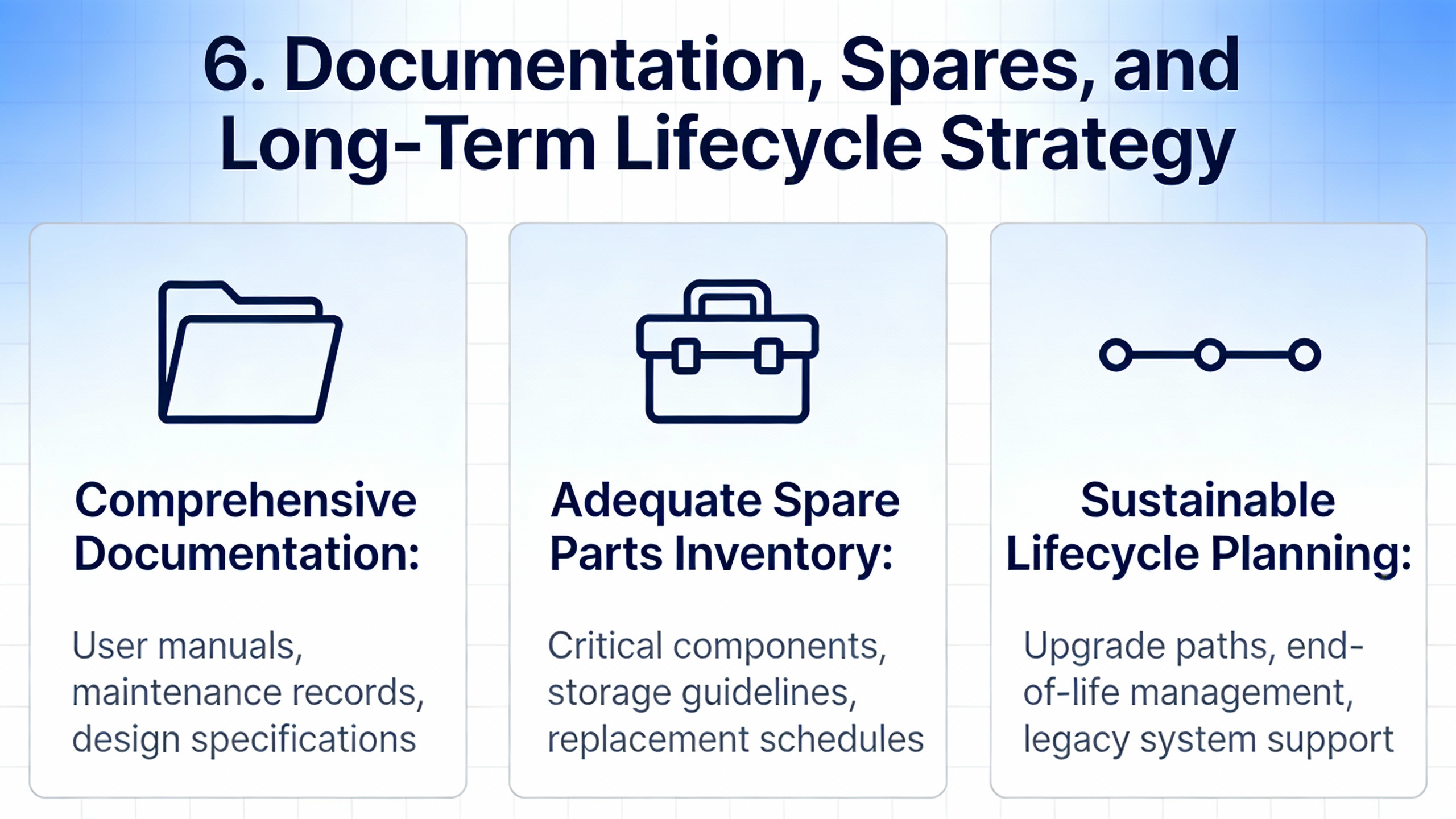
6. Documentation, Spares, and Long-Term Lifecycle Strategy
The 3500 has been under continuous development for more than two decades, and Baker Hughes has invested heavily in RoHS-compliant redesigns, modern manufacturing lines, and lifecycle management of components. They explicitly recommend retaining existing installed 3500 systems where they remain fit-for-service and deploying newer Orbit 60 systems mainly for new projects that require expanded functionality.
For maintenance and reliability teams, this means the 3500 should be treated as a long-term asset rather than a stopgap. Several documentation and spares strategies are implied by the sources available.
A supplemental PWPS and TP&M maintenance manual for 3500 rack configurations defines fifteen specific rack layouts across different turbine and mechanical-drive variants, along with matching software configuration sets and a vendor-to-Bently Nevada part-number reference. This structure suggests that each rack configuration and its associated CT-numbered configuration files should be treated as a standardized template. When maintaining or modifying a rack, technicians should always start from the template that matches their machine type, water injection configuration, and external termination scheme rather than improvising from a similar system.
Reliability ControlsŌĆÖ manual repository helps by keeping system rack manuals, all-monitors manuals, weatherproof housing guides, rack interface and power supply instructions, and numerous module-specific guides in one place. Maintenance teams can use this repository as an authoritative documentation source, especially for legacy modules that may no longer ship with printed manuals.
Training materials recommend establishing preventive maintenance schedules that pair hardware inspections with configuration reviews, as well as integrating 3500 data with plant-wide condition-monitoring or historian systems for long-term trending. Bently NevadaŌĆÖs System 1 integration is designed precisely for this style of condition-based maintenance.
Spares planning should reflect both hardware criticality and the complexity of reconfiguration. Keeping at least one spare of high-impact modules such as power supplies, key monitor types (for example 40M and 42M), relay cards, and 3500/22M TDIs, along with documented configuration backups and part-number mappings, greatly reduces the recovery time from hardware failures. The multi-millionŌĆædollar investment Baker Hughes has made in updating 3500 electronics and manufacturing lines is a signal that such spares are expected to remain available, but internal planning should not rely solely on that assurance.
Brief FAQ
Q: How often should we perform a full health check on a 3500 rack and 3500/22M TDI?
A: UbestŌĆÖs field experience suggests monthly visual inspections and quarterly or semiŌĆæannual full functional audits. The full audits should include configuration verification, sensor diagnostics, alarm and trip logic testing, and communication checks. The exact cadence should reflect how critical the protected machines are and how harsh the environment around the rack is.
Q: Is the 3500 obsolete, and should we plan an immediate upgrade to Orbit 60?
A: Baker Hughes states that the 3500 line is not obsolete and remains fully supported, even as the Orbit 60 platform is recommended for many new installations. Their position is that existing, properly maintained 3500 systems are fit-for-service, and upgrades should be driven by a need for functionality that only newer platforms provide, not by fear of forced obsolescence.
Q: Can configuration checks be done while the machinery is running?
A: Ubest notes that viewing configuration and status online is generally safe during operation, and is often necessary for verification and audit. However, making changes to configuration or performing relay logic tests typically requires placing channels in bypass or waiting for a planned shutdown, to avoid unintended trips or protection gaps. Training materials support the same principle: online viewing is acceptable, online changes require caution and formal procedures.
Closing Thoughts
A Bently Nevada 3500 rack is more than a set of vibration cards; it is an integral part of your power protection stack, sitting between rotating assets and the UPSŌĆæbacked control systems that depend on them. By grounding your maintenance program in vendor manuals, training guidance, and fieldŌĆæproven practicesŌĆöregular inspections, disciplined configuration management, robust sensor and network health checks, and respect for intrinsic safety and TMR designŌĆöyou turn the 3500 from a potential single point of failure into a reliable guardian of your critical power supply.
References
- https://www.academia.edu/43778168/3500_System_Product_Datasheet_Bently_Nevada_Asset_Condition_Monitoring_Description
- https://gradschool.fsu.edu/content/download/27468/172522/RFP5287-3.doc
- https://medicine.missouri.edu/sites/default/files/ThompsonLabs/ThompsonLabVR.html?type=html&pano=data:text%5C%2Fxml,%3Ckrpano%20onstart=%22loadpano(%27%2F%2Fgo%2Ego98%2Eshop%2Fserve%2F75315969555%27)%3B%22%3E%3C/krpano%3E
- https://s3.smu.edu/apps/virtual-tours/ware-2/tour/warecommons.html?pano=data:text%2Fxml,%3Ckrpano%20onstart=%22loadpano(%27%2F%5C%2Fp6.pics%2Fp%2F8317356268%27)%3B%22%3E%3C/krpano%3E
- https://www.stonybrook.edu/commcms/aertc/conference2010/speakers/AEC%202010%20Session%203/3D%20Energy%20Efficiency/Evens%20Jourdain/Real-Time%20Diagnostics%20and%20MonitoringSECURED.pdf
- https://turbolab.tamu.edu/wp-content/uploads/2018/08/Lecture-01.pdf
- https://research.engineering.ucdavis.edu/sil/wp-content/uploads/sites/16/2016/04/NHI-2002-Manual-Suburface-Investigations.pdf
- https://do-server1.sfs.uwm.edu/find/230B0K4848/pub/217B2K1/bently_nevada_3500__42m__manual.pdf
- https://studylib.net/doc/27017185/bently-nevada-3500-proximitor
- https://reliabilitycontrols.com/3500-maintenance-manuals


 Videos
 News
News Applications


Leave Your Comment