Distributed Control Systems sit at the heart of many industrial and commercial power systems. In power plants, microgrids, and large UPS and inverter installations, the DCS is often what decides whether a disturbance becomes a controlled event or a fullŌĆæblown outage. Getting the technical parameters right at specification time is therefore a reliability decision, not just an automation decision.
Drawing on guidance from vendors and practitioners highlighted by sources such as ABB, GlobalSpec, Industrial Equipment News, Automation Community, and Just Measure It, this article walks through the key DCS system specifications and technical parameters that matter most for powerŌĆæfocused applications: UPS, inverters, and power protection equipment.
Why DCS Technical Parameters Matter in Power and UPS Environments
A DCS is an industrial automation architecture where control intelligence is distributed across many networked controllers, I/O modules, and HMIs instead of being concentrated in a single computer. Automation Community and LLumin describe how these distributed controllers monitor and control specific processes or plant areas continuously, feeding data into central operator workstations.
For power and powerŌĆæprotection systems, that architecture maps naturally onto the way facilities are built. You have distributed assets such as generators, inverters, UPS strings, switchgear, static transfer switches, and protection relays, all spread across several rooms or buildings. Using a DCS, you can place controllers close to these assets while still coordinating them from a central control room.
Several sources converge on the same benefits that are particularly important for power systems:
DCS architectures improve reliability and fault tolerance because the failure of one controller or component does not typically bring down the entire system. GlobalSpec and Zintego both highlight redundancy and distributed intelligence as central design features.
DCSs are built for continuous and batchŌĆætype processes, which is exactly how power plants run. Automation Community notes that process industries such as power generation rely on DCS to keep thousands of field points synchronized and stable.
DCS platforms integrate highŌĆælevel functions such as data historians, alarm management, and reporting, which are essential when you have to justify uptime, power quality, and incident handling to internal stakeholders and regulators.
For a UPS or inverterŌĆæheavy facility, this means you can move from treating each system as a standalone ŌĆ£boxŌĆØ to orchestrating them as part of a coherent, monitored, and defended power system.
Architectural Levels: From Field Devices to Enterprise Planning
LLumin and Zintego describe a fiveŌĆælevel DCS hierarchy that is a useful way to structure your specifications and technical parameters. Even if your vendor uses different naming, the concepts are similar.
At Level Zero you define parameters for field devices: sensors, transmitters, and actuators. In a power system this includes current and voltage transformers, temperature sensors on transformers or UPS modules, breaker position contacts, and motorŌĆæoperated disconnects. The specification here focuses on signal types, signal conditioning, accuracy, environmental ratings, and how many I/O points you need per area.
At Level One you specify I/O modules and smart devices. These modules interface field signals to the controllers. You should define analog versus discrete channel counts, isolation, diagnostic features, and whether remote I/O drops are needed in each electrical room. Sources like GlobalSpec emphasize that many DCS components can operate as standalone devices, which gives you flexibility to reconfigure or reuse hardware as your site evolves.
At Level Two you define supervisory computers and operator HMIs. LLumin notes that these systems collect data from controller nodes and present process graphics, alarms, and trends. Your specification here covers the number of operator stations, display resolution and layout expectations, alarm banner behavior, trend resolution, and historian connections.
At Level Three you define production coordination. In power systems this level typically handles loadŌĆæsharing logic, generator dispatch, UPS operating modes, and maintenance workflows. Automation Community and Confluent both stress how DCS platforms increasingly integrate with MES or maintenance systems, so it makes sense to define how productionŌĆælevel applications will access and use DCS data.
At Level Four you define integration to enterprise planning and scheduling. For a power plant this might include links to a utilityŌĆÖs energy management system or to a campus facilities management platform. For a data center or hospital it might include integration to corporate asset and maintenance management systems, similar to what LLuminŌĆÖs CMMS+ is designed to support.
Thinking in levels forces you to specify not only individual components, but how information flows from field devices all the way up to business decisions.

Controllers and I/O: Performance Parameters That Actually Matter
GlobalSpec and Zintego both point out that a DCS distributes control intelligence across multiple controllers. These controllers are not just simple logic modules; they run advanced control strategies, execute alarms, and manage local redundancy. When you specify a DCS for power systems, the controller and I/O parameters deserve careful attention.
From a performance standpoint, GlobalSpec notes that PLCs often execute logic in the neighborhood of about 10 milliseconds, while DCS control loops are commonly engineered with scan times roughly in the 100 to 500 millisecond range. The DCS trades some raw speed for richer redundancy, integrated alarming, and more processŌĆæoriented tools. For breaker interlocks and UPS transfer sequences that must be deterministic and fast, you may still select PLCs or dedicated protection relays and then integrate them into the DCS. For slower supervisory functions such as tap changer control, battery temperature monitoring, or generator loading, DCS scan times are generally more than adequate.
The more important parameters to define in your specification are:
Controller capacity in terms of expected number of loops or function blocks per controller, based on the DCS guides referenced by Just Measure It. Zintego underscores that DCS deployments commonly scale from hundreds to thousands of devices and control loops, so scalability needs to be explicit rather than assumed.
I/O density and distribution. Sources like GlobalSpec and LLumin highlight the role of networked I/O, so you want to define how many remote I/O stations you expect, maximum cable runs or fiber segments between electrical rooms and control rooms, and the mix of analog, digital, and specialŌĆæpurpose signals (for example, highŌĆæspeed digital inputs from protective relays).
Diagnostics and hotŌĆæswap capabilities. Schneider ElectricŌĆÖs repair guidance notes that failures often cluster in I/O modules and power supplies. Specifying builtŌĆæin diagnostics, hotŌĆæswappable modules, and clear indication of module health will shorten mean time to repair when something does fail.
When you match controller performance and I/O distribution to the dynamic behavior of your power system, you avoid the two extremes of overŌĆæspecifying highŌĆæspeed logic where it is not needed or underŌĆæspecifying supervisory controllers and then fighting capacity limits for the life of the plant.
Communication Networks and Redundancy
The DCS communication network is the nervous system of your power system controls. Automation Community and LLumin emphasize that DCS networks must support seamless, reliable, and realŌĆætime data transfer between controllers, I/O, and the central control room. GlobalSpec adds that standard industrial networks, such as EthernetŌĆæbased protocols and fieldbuses, are commonly used.
Your specification should address at least three aspects of the network.
First, protocol and topology. You will normally choose standard industrial Ethernet and field protocols such as ModbusŌĆæbased variants or other widely used industrial networks referenced by GlobalSpec and Zintego. For power equipment such as UPS systems, inverters, and digital protective relays, ModbusŌĆæstyle and Ethernet protocols are common. Defining protocol expectations early keeps you from relying on awkward protocol converters later.
Second, redundancy. GlobalSpec describes redundancy as a core design feature, with backup processors and redundant paths used to increase reliability. Zintego goes further, describing dualŌĆæredundant controllers, power supplies, and communication paths as defining characteristics of DCS design. In a power environment this often translates into dual fiber or copper network rings between buildings or switchgear rooms, redundant switches, and dual network ports on controllers.
Third, segmentation. Multiple sources, including the DCS modernization guidance and DCS maintenance best practices, recommend clear segmentation between control networks, safety or protection networks, and corporate IT networks. That segmentation, enforced by firewalls and DMZ architectures, becomes even more important as you add remote monitoring, CMMS integration, and cloudŌĆæbased analytics such as the streaming architectures discussed by Confluent.
A simple way to test whether your specification is robust is to ask what happens if you lose one network switch or one fiber. If the answer is ŌĆ£We lose all visibility of the UPS plant,ŌĆØ then your redundancy parameters are likely underŌĆæspecified.

Control Performance, Availability, and Alarm Management
From a power system reliability perspective, three sets of parameters typically define whether the DCS supports your operational goals: control performance, availability, and alarm management quality.
Control performance parameters include scan times, loop execution order, and time stamping resolution. GlobalSpecŌĆÖs distinction between PLC and DCS performance is helpful here. For highŌĆæspeed protection you rely on relays and UPS internal logic and feed their status into the DCS. For slower loops such as generator speed and load control, transformer temperature control, and battery room ventilation, the DCS is the right place for closedŌĆæloop logic. When specifying scan times, it is more productive to group similar loops and assign practical scan rates than to insist on the fastest possible rate for every loop.
Availability parameters are largely driven by redundancy. Automation CommunityŌĆÖs maintenance guidance and GlobalSpec both recommend redundant controllers, sensors, communication networks, and even power supplies for critical components. In a power system context this means you will often ask for redundant controllers for generator and switchgear control, redundant network paths between critical buildings, and independent DC supplies supporting the DCS itself. Schneider Electric RepairŌĆÖs experience that failures cluster around I/O and power supplies supports treating these items as deliberate design points rather than afterthoughts.
Alarm management parameters have a direct effect on whether operators can prevent small disturbances from cascading. Industrial Equipment News, summarizing guidance from standards such as ANSI/ISAŌĆæ18.2, emphasizes that alarms should be reserved for conditions that require operator action, with other messages treated as alerts or notifications. Poorly designed alarm systems can flood operators with chattering alarms and make it difficult to see the one breaker failure or UPS warning that truly matters.
In practice this means specifying an alarm philosophy up front. For example, you might require that all UPS and inverter alarms be classified by priority and consequence, that every alarm include a short, actionŌĆæoriented message, and that nuisance alarms be suppressed or conditioned. LLumin and Just Measure It both highlight the role of HMIs and configuration tools in bringing these philosophies to life. Including these expectations as part of your DCS technical specification helps vendors configure a manageable alarm system rather than a noisy one.
HMI and Operator Interface Specifications
HumanŌĆōmachine interfaces are central to DCS value. The HMI is where operators see the state of the power system, acknowledge alarms, and initiate transfers or overrides. Automation Community and LLumin describe how modern HMIs present trends, bar charts, and realŌĆætime data in ways that make complex processes intuitive. Industrial Equipment News, using ValmetŌĆÖs D3 system as an example, illustrates how standardization of color, alarm banners, and layout improves situational awareness.
Key HMIŌĆærelated parameters you should consider specifying include:
Number and location of operator workstations, particularly if you have multiple control rooms for generation and distribution.
Graphics standards: for instance, highŌĆæperformance HMI concepts where muted colors are used for normal conditions and strong colors like red and yellow are reserved for alarms, as advocated in highŌĆæperformance HMI guidance from vendors and industry associations.
Alarm presentation rules, including where alarm lists appear on the screen, how priorities are colorŌĆæcoded, and how alarm shelving or suppression is indicated.
Trend and historian integration so that operators can pull up voltage, current, or breaker operation histories without leaving the main screens.
The lesson from Industrial Equipment News is that when every engineer designs screens their own way, operators pay the price. A specification that calls for standardized, wellŌĆædocumented HMI design patterns is a reliability investment, not just a cosmetic one.
Integration Parameters for UPS, Inverters, and Power Protection
The DCS is rarely the only control platform in a power facility. You will often have UPS controllers, inverter controls, generator controllers, digital protective relays, meters, and sometimes separate PLCs running local sequences. Several sources highlight how DCSs are strong at integration, including Automation CommunityŌĆÖs notes on interfacing with ERP and maintenance systems, ConfluentŌĆÖs description of streaming DCS data into business platforms, and GlobalSpecŌĆÖs emphasis on centralizing maintenance and monitoring.
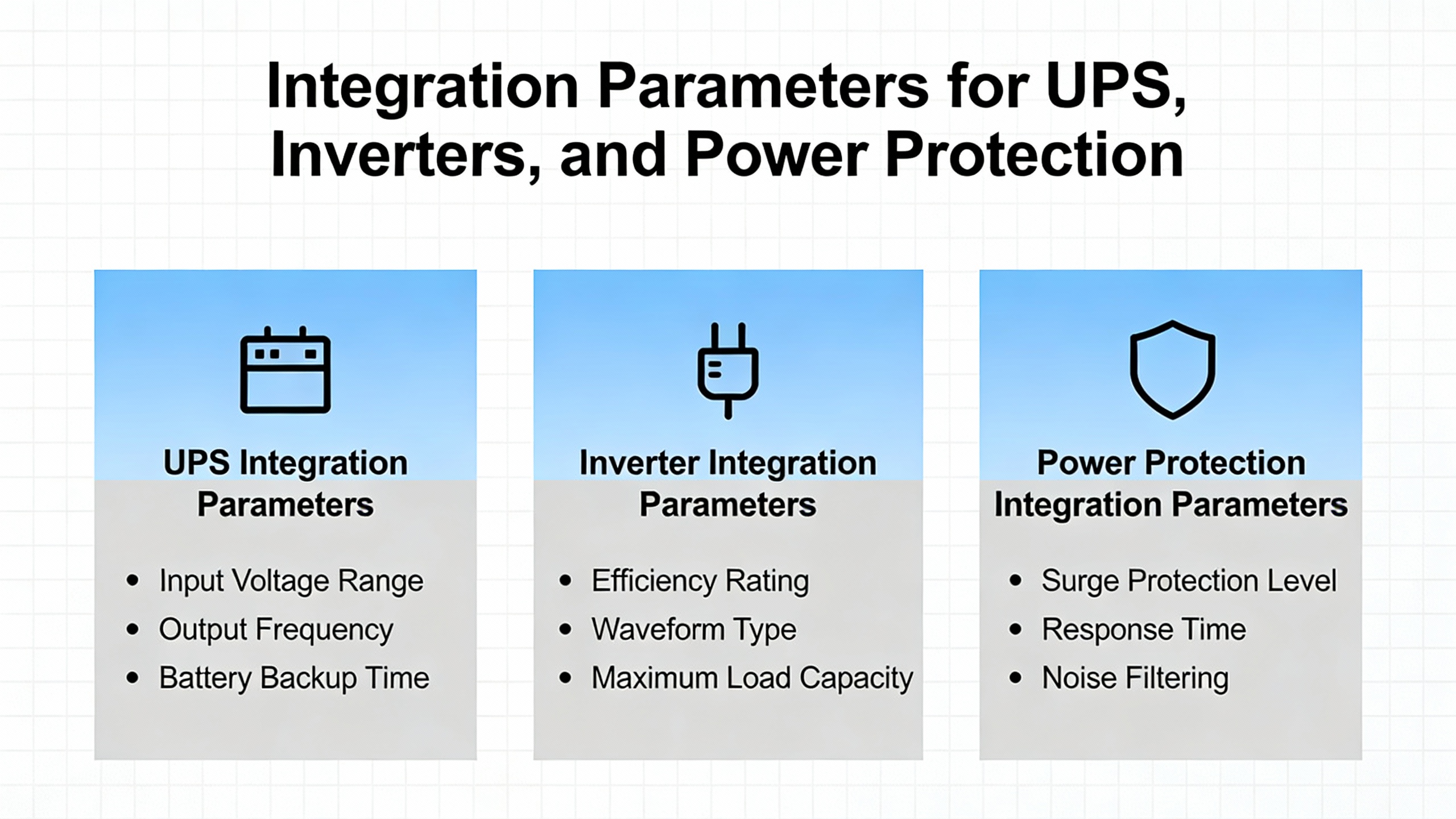
For power systems, the integration parameters that belong in the DCS specification typically include:
Interface types for UPS and inverter systems. Many modern systems offer serial, Ethernet, or fieldbus connections. Defining which interface will be used and what data points are required avoids later surprises where critical alarms are only available on a local panel.
Integration with protective relays and meters, usually via protocols such as those mentioned by GlobalSpec and Zintego. Your specification should identify which relays must share status and analog values with the DCS and which are strictly standŌĆæalone for safety reasons.
Event and fault recording expectations. For example, when a UPS transfers from utility to battery, you likely want breaker operations, voltage sags, and key alarms to appear in the DCS historian with consistent time stamps. ConfluentŌĆÖs discussion of realŌĆætime streaming from DCS to business systems illustrates how valuable these event streams can be for both operations and analytics.
Integration with maintenance and asset management systems. LLuminŌĆÖs CMMS+ example shows how a CMMS can consume DCS data to drive predictive maintenance, spare parts planning, and compliance reporting. Including explicit tags and data structures for CMMS integration in the DCS specification makes that future link much easier to realize.
An effective way to validate your integration parameters is to walk through a realistic UPS event on paper and confirm what each system needs to know, when it needs to know it, and how the DCS will participate in the sequence.
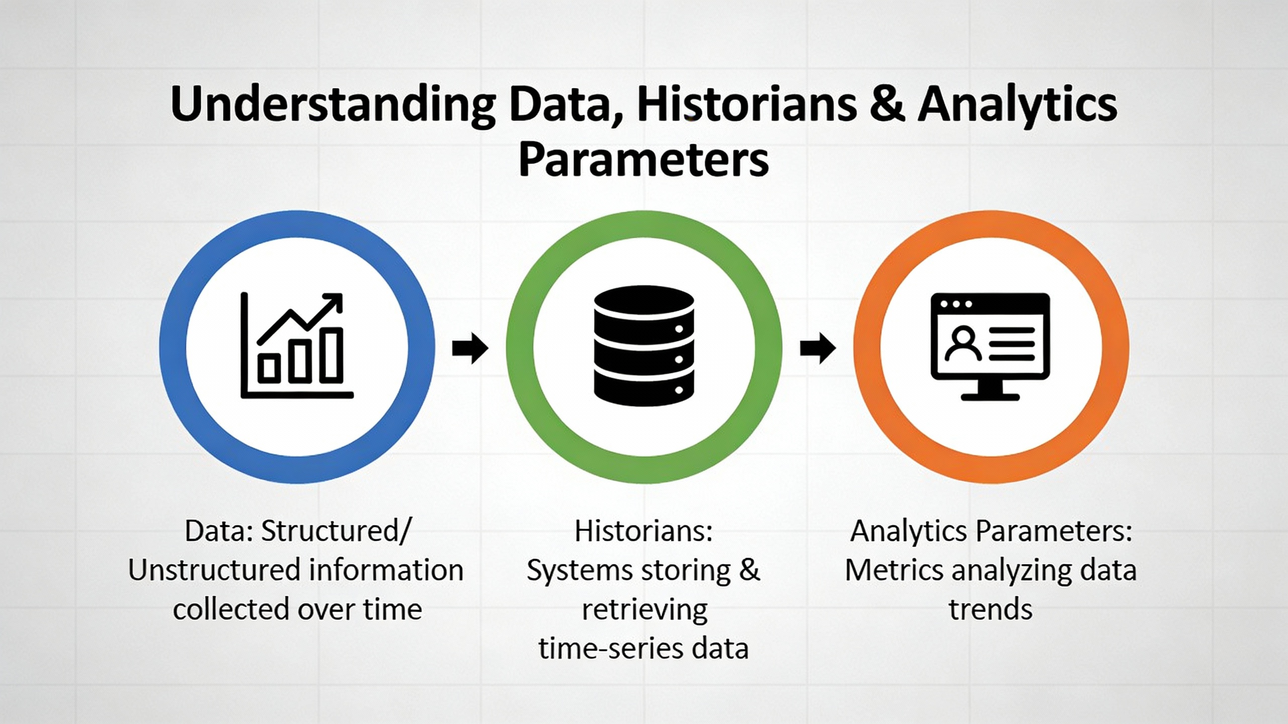
Data, Historians, and Analytics Parameters
All major DCS vendors now treat data as a firstŌĆæclass design element. Automation Community references data historians built into DCS platforms, while LLumin and Confluent discuss how DCS data feeds CMMS and realŌĆætime streaming platforms.
Your specification should address at least four dataŌĆærelated dimensions.
Sampling and storage. Define which power system variables need longŌĆæterm storage and at what granularity. For example, feeder currents and voltages, UPS load and battery health indicators, and generator performance metrics are common candidates.
Retention periods. Regulatory and contractual obligations sometimes require years of data for power quality and event analysis. You should decide how long raw and aggregated data needs to be retained and where (onŌĆæpremises, offsite, or both).
Data access. ConfluentŌĆÖs guidance on treating DCS data as part of a streaming architecture is a reminder to specify how other applications will consume your DCS data. That might include OPCŌĆæstyle interfaces, historian replication, or event streaming buses.
Analytics hooks. If you intend to implement predictive maintenance or advanced analytics later, it is worth specifying that key equipment health indicators and alarm events be standardized across generator, UPS, and inverter assets. That consistency simplifies future models and dashboards.
Treating data specifications as part of the DCS technical parameters rather than an afterthought is increasingly critical as power systems become more connected and more scrutinized.
Maintainability, Cybersecurity, and Lifecycle Specifications
Automation CommunityŌĆÖs DCS maintenance guidance makes a strong case that maintenance is not optional. Without a structured program of inspections, backups, updates, and performance monitoring, even the bestŌĆæspecified DCS will drift into unreliability. Schneider Electric RepairŌĆÖs focus on repairing rather than ripping and replacing DCS components, and the DCS modernization guidance about phased upgrades, both reinforce the value of lifecycle thinking.
At specification time, that means capturing maintainability parameters such as:
Requirements for configuration backups and tested restore procedures.
Expectations for builtŌĆæin diagnostics on controllers, I/O modules, power supplies, and networks.
Spare parts and vendor support strategies, including whether you expect access to local support and defined response times.
Cybersecurity parameters also need to be explicit. DCS modernization and DCS configuration guidance from Just Measure It point to measures such as network segmentation, firewalls between control and corporate networks, roleŌĆæbased access control, and controlled remote access. Automation CommunityŌĆÖs maintenance article adds intrusion detection and regular security audits to the mix. Standards such as IEC 62443 for industrial control system security, which are referenced in modernization discussions, can give structure to these requirements.
Cybersecurity and maintainability are not addŌĆæons. In many incident investigations, the root causes can be traced back to unpatched systems, poorly protected remote access, or undocumented configuration changes. When you define these expectations as core technical parameters, you give your operations and IT teams a clear target to aim at.

Summary Specification Themes for PowerŌĆæFocused DCS Projects
While every project is unique, a pattern emerges when you line up the guidance from Automation Community, GlobalSpec, Industrial Equipment News, LLumin, Just Measure It, and others. Successful DCS specifications for power and UPS environments consistently do three things well.
They are architectureŌĆæaware, explicitly defining how field devices, I/O, controllers, HMIs, and enterprise systems will interact.
They are reliabilityŌĆædriven, using redundancy, alarm standards such as ANSI/ISAŌĆæ18.2, and clear HMI practices to support operators under stress rather than overwhelm them.
They are lifecycleŌĆæconscious, treating maintenance, cybersecurity, CMMS integration, and modernization paths as firstŌĆæorder design elements, not change orders.
The table below summarizes several of the most important parameter categories and why they matter in power and powerŌĆæprotection applications.
| Parameter Category | What It Defines | Why It Matters In Power and UPS Systems |
| Architecture and levels | How field devices, I/O, controllers, HMIs, and enterprise tools are structured | Ensures generator, UPS, inverter, and protection devices are coordinated instead of operating as isolated islands |
| Controller and I/O performance | Loop execution, I/O density, diagnostics, distribution | Balances fast protection handled by relays and PLCs with robust DCS supervision and scalability |
| Network and redundancy | Protocols, topology, redundant paths, segmentation | Prevents a single network failure from blinding the control room and supports high availability for critical loads |
| Alarm and HMI standards | Alarm philosophy, HMI layout, graphics standards | Keeps operators focused on the few alarms that matter when power quality or availability is threatened |
| Integration and data | Interfaces to UPS, inverters, relays, CMMS, historians, streaming platforms | Enables realŌĆætime situational awareness and longŌĆæterm analytics across the entire power system |
| Maintenance and cybersecurity | Backup, diagnostics, spares, security architecture and controls | Reduces unplanned outages due to neglected updates, configuration drift, or cyber incidents |
Brief FAQ
How is a DCS different from PLC or SCADA in a power system?
GlobalSpec and Zintego both emphasize that PLCs excel at fast, discrete machineŌĆælevel control, while DCSs are designed for large, continuous processes with many analog loops and strong redundancy. In a power plant or large UPS facility, protection relays and PLCs typically handle the fastest and most safetyŌĆæcritical actions, such as fault clearing and internal UPS logic. The DCS coordinates slower supervisory functions, aggregates data, manages alarms, and gives operators a plantŌĆæwide view. SCADA systems, as described by LLumin, tend to focus on wideŌĆæarea supervisory control and data acquisition, often across dispersed assets such as remote substations, while DCS stays closer to the plant.
When is a full DCS overkill for UPS and inverter controls?
If your facility has a small number of UPS systems or inverters, all in one room and with limited coordination needs, the cost and complexity of a full DCS platform may not be justified. Sources like GlobalSpec note that DCSs carry higher cost and sophistication that are best suited to continuous, highŌĆævalue, safetyŌĆæcritical processes. PLCs or vendorŌĆæsupplied controllers with simple monitoring panels may be enough for smaller sites. As the number of devices, control loops, and coordination requirements grows into the hundreds or thousands, and as you add integration to CMMS and analytics platforms, the balance usually shifts in favor of a DCS.
How can I align DCS specifications with future digitalization projects?
Automation CommunityŌĆÖs discussion of Industry 4.0 trends and ConfluentŌĆÖs focus on streaming architectures both point toward treating DCS data as a strategic asset. At specification time, that means standardizing tag naming, defining historian and event data requirements, selecting open protocols, and articulating how maintenance and business systems will consume DCS data. If you treat those as core technical parameters rather than ŌĆ£future options,ŌĆØ your DCS will be ready to feed digital twins, predictive maintenance models, and enterprise dashboards without major rework.
A wellŌĆæspecified DCS does more than close control loops; it becomes part of your power systemŌĆÖs protection strategy. When you define architecture, performance, integration, and lifecycle parameters with the same rigor you apply to UPS and protection equipment, you give your operators and maintenance teams a platform they can trust when the lights flicker and the clock is ticking.
References
- https://pdxscholar.library.pdx.edu/cgi/viewcontent.cgi?article=1785&context=ece_fac
- https://en.wikipedia.org/wiki/Distributed_control_system
- https://www.se.rit.edu/~se442/slides/class/01-Introduction.pdf
- https://murray.cds.caltech.edu/images/murray.cds/3/3b/Eeci-sp09_L5_distributed.pdf
- https://do-server1.sfs.uwm.edu/exe/3Q8J182310/ppt/5Q9J518/distributed_control_system_dcs-supervisory_control-computer.pdf
- https://www.automate.org/news/the-evolution-of-distributed-control-systems-dcs-from-legacy-architecture-to-intelligent-automation-109
- https://www.plctalk.net/forums/threads/plc-dcs-best-practices.101109/
- https://automationcommunity.com/basics-of-distributed-control-systems/
- https://www.controleng.com/considerations-for-choosing-the-right-control-system-platform/
- https://www.csesolutionsindia.com/what-is-a-distributed-control-system/


 Videos
 News
News Applications


Leave Your Comment