Industrial boilers sit at the heart of many power and process plants. They feed steam turbines, drive large process loads, and keep critical facilities online. As a reliability advisor focused on power systems, I often see that the real risk to uptime is not the boiler shell or the turbine downstream, but the way the flame is supervised and shut down. That layer is the burner management system, and when it is weak, even a small disturbance can become a major safety or availability event.
This article walks through how burner management systems (BMS) protect industrial boilers, how they differ from combustion control, what standards really matter, and how to design or retrofit a system that is both safe and highly reliable. The perspective here is practical: what works in real boiler rooms, not just in diagrams and standards books.
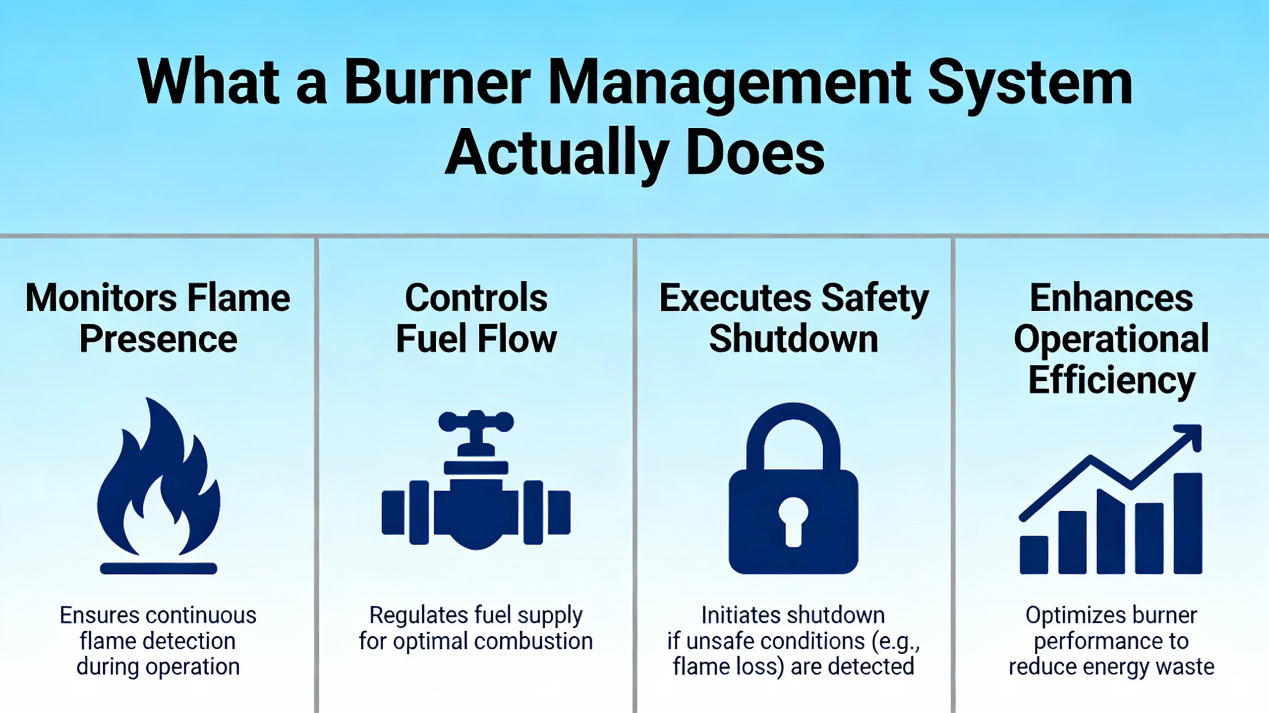
What a Burner Management System Actually Does
At its core, a burner management system is a safety control system that decides when it is safe to have a flame in a furnace and when fuel must be shut off. Sources such as the Kolmetz Handbook of Process Equipment Design and technical guidance from Stanyan Hill describe the BMS as a dedicated layer that permits firing only when a defined set of safe conditions and interlocks are satisfied. When any of those conditions is violated, the BMS trips fuel and drives the boiler to a predefined safe state.
Unlike the combustion control loop that modulates fuel and air for efficiency, the BMS has a binary mindset: either conditions are proven safe, or fuel is off. Typical BMS responsibilities, as summarized by Stanyan Hill and Turbine Logic, include managing the entire firing sequence, starting from standby, through preŌĆæpurge, ignition trials for pilot and main flame, release to modulation, and finally postŌĆæpurge and shutdown. Throughout that sequence, the system is constantly validating interlocks and flame status.
A simple example illustrates why this matters. Consider an industrial watertube boiler supplying steam to a turbine that feeds essential plant buses. During a cold start, the BMS first drives the forced-draft fan to high fire with fuel valves shut, purging the furnace for a defined time. Only when purge flow, damper position, and low-fire positioning are proven does the system energize the ignition transformer and pilot valve. The pilot flame must be proven within about ten seconds, as described in classic boiler safety references like TechTransferŌĆÖs discussion of CB-Hawk, or the system locks out. If the pilot is stable, the BMS opens main fuel valves and again looks for a valid flame within a tight time window. Any missed proof results in an immediate trip. This conservative sequencing is what stands between a clean light-off and an explosive fuel accumulation.
That same logic operates during normal running. If flame scanners lose the flame, if combustion air drops out, or if critical limits such as high furnace pressure or high stack temperature are exceeded, the BMS closes fuel valves and triggers a purge and lockout. The objective is always the same: prevent an uncontrolled mixture of fuel and air from finding an ignition source.
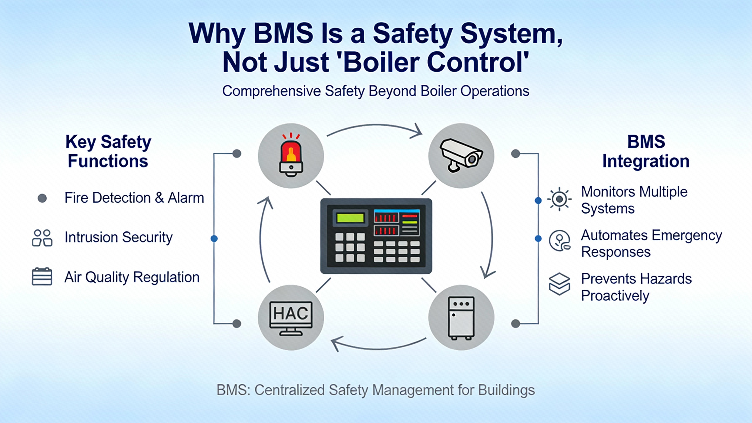
Why BMS Is a Safety System, Not Just ŌĆ£Boiler ControlŌĆØ
Several sources emphasize that the BMS must be independent of the normal process control system. aeSolutions and NFPA guidance stress maintaining a clear separation so that production pressures cannot easily override safety trips. Kolmetz notes that many historical heater and boiler accidents trace back to unsatisfied permissive interlocks and unsafe restarts after trips, not to exotic mechanical failures.
In modern boiler installations you typically see a structure like this. The combustion control (often tied into a DCS or PLC) handles load demand, airŌĆōfuel ratio control, and drum level. The burner management system stands alongside it as a dedicated safety logic solver, watching flame, air flow, fuel trains, and safety limits. It has its own master fuel trip, hardwired shutdown pushbutton, and lockout logic.
From a power-system viewpoint, this separation is critical. When the BMS trips, you want the plantŌĆÖs electrical system to react in a controlled way: load shedding, turbine runback, or hot standby assets picking up the slack. When the electrical system misbehaves, you still want the BMS to be powered from a stable, protected source, typically backed by an industrial UPS, so it can complete purges and fail-safe shutdowns instead of freezing mid-sequence. Treating the BMS as a safety instrumented system rather than a mere boiler controller is the first step toward that level of resilience.
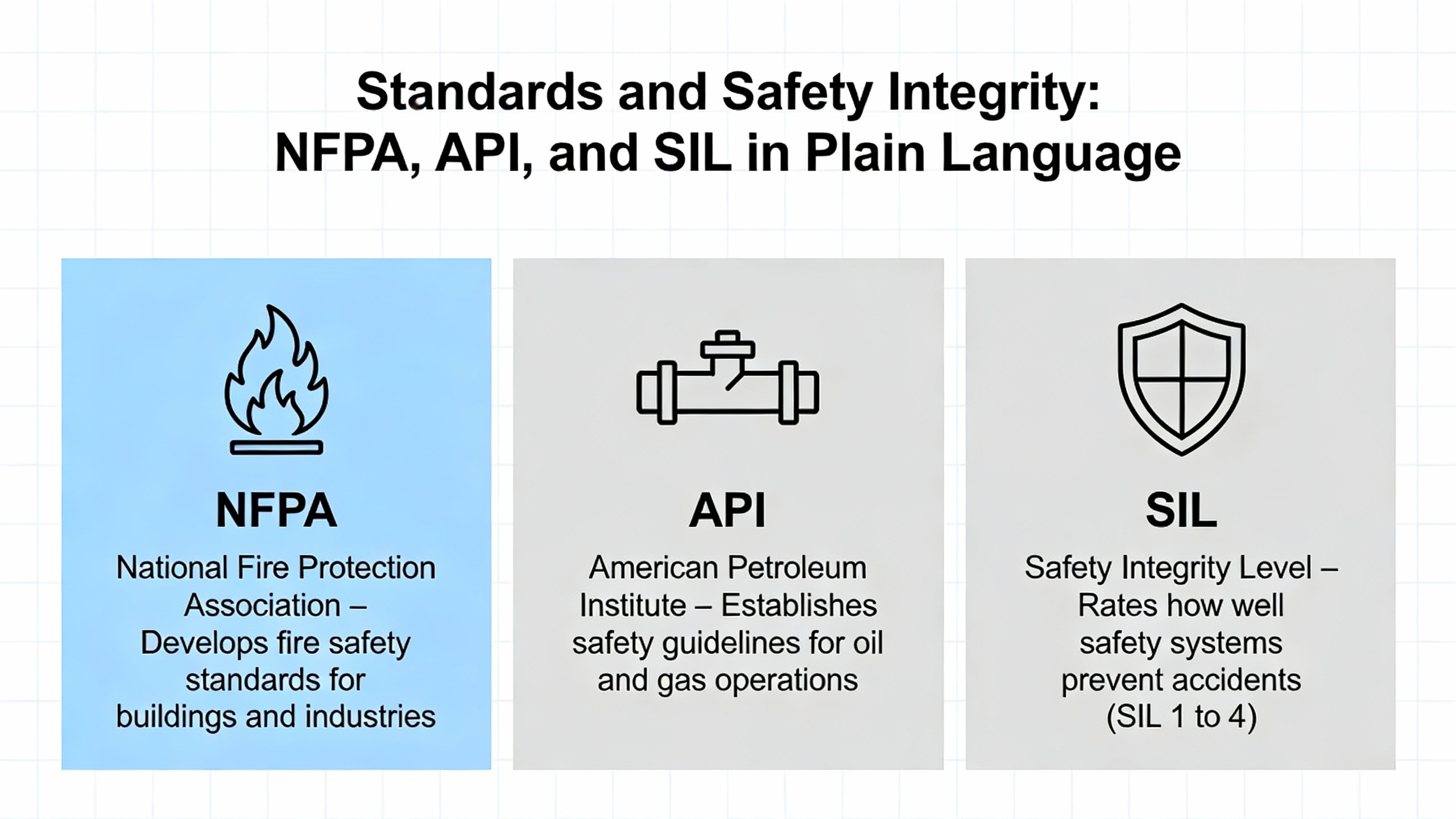
Standards and Safety Integrity: NFPA, API, and SIL in Plain Language
Facilities often ask what standards really matter for BMS. Profire Energy and Control & Instrumentation summarize a landscape that looks complex but is manageable when you break it down.
For industrial boilers above roughly 3.7 MW input, NFPA 85 is the primary standard. It defines requirements for interlocks, purge times, ignition, flame detection, operator training, and periodic testing. For other fired equipment, NFPA 86 covers ovens, dryers, and many furnaces, while NFPA 87 addresses thermal and process fluid heaters. In petrochemical and refinery service, API 538 and API 556 supplement NFPA by addressing boiler and heater design, instrumentation, and protective functions.
On top of that, regional codes such as CSA B149.3 in Canada, EN 746ŌĆæ2 and ISO 13577ŌĆæ2 in Europe, and AS 3814 in Australia add specific requirements for fuel trains and furnace safety. Electronic burner controls themselves are often qualified to IEC 60730ŌĆæ2ŌĆæ5, which sets construction and performance criteria.
Modern BMS discussions increasingly involve Safety Integrity Level (SIL), as defined in IEC 61508 and IEC 61511. SIL is a measure of how much risk reduction a safety instrumented function provides. A recent study on burner shutoff valves presented at an E3S conference (summarized in the notes under the Academia article) modeled a BMS loop using Reliability Block Diagrams and calculated the average probability of failure on demand, or PFDavg. In an initial configuration with non-SIL-rated field devices, the calculated PFDavg was on the order of 9.8├Ś10Ōü╗┬╣ per year for the shutdown function, which does not achieve even SIL1 in low-demand mode.
When the design was upgraded to use SIL2-certified pressure transmitters and valve positioners, still in a redundant one-out-of-two architecture, the same exSILentia analysis produced a PFDavg around 1.6├Ś10Ōü╗Ōü┤ per year. That level of risk reduction is consistent with a SIL3 shutdown function. The striking point from the paper is that the shutoff valve dominated the risk profile: in the initial design it contributed more than ninety percent of the loop PFDavg. Simply put, if your main fuel shutoff valves are not reliable and testable, the best logic solver in the world cannot rescue your safety case.
From a practical perspective, this means your BMS design must align three things: codes such as NFPA 85 or 86, functional safety guidance from IEC 61508/61511, and realistic reliability data for field devices, especially valves and sensors.
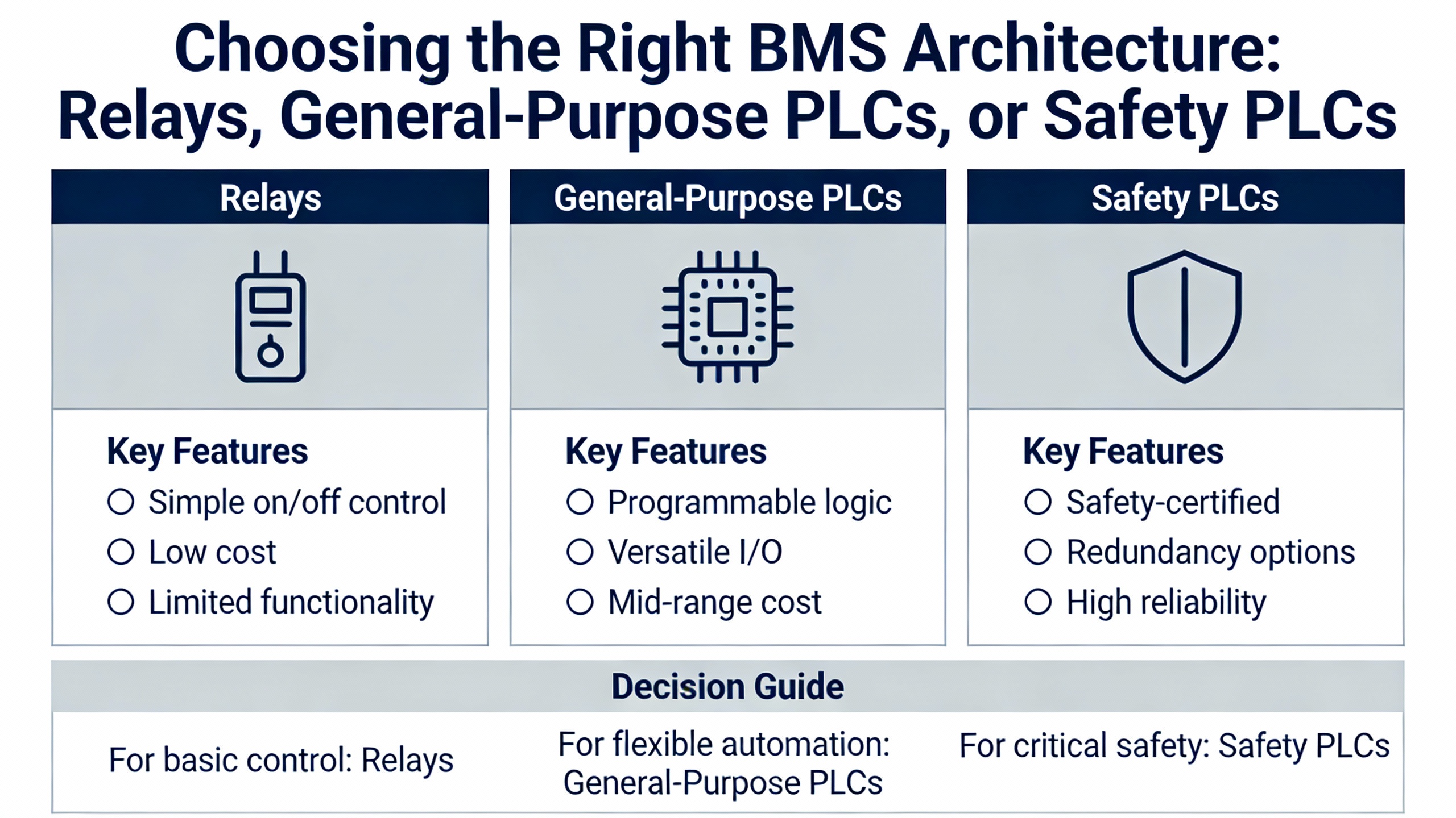
Choosing the Right BMS Architecture: Relays, General-Purpose PLCs, or Safety PLCs
You can implement burner management logic in several ways, each with tradeoffs in safety, flexibility, and maintainability. Stanyan Hill, Emerson, and Kolmetz give complementary perspectives that can be summarized usefully.
Here is a compact comparison.
| BMS platform | Typical use case | Key strengths | Main limitations |
| Microprocessor flame safeguard relay | Single or simple unisonŌĆæfired burners | Proven, relatively low cost, code-aware hardware | Limited logic flexibility, added relays for sequencing |
| General-purpose PLC | Industrial watertube boilers, custom sequences | Flexible, integrates with plant control, configurable diagnostics | Requires careful design to meet NFPA and SIL intent |
| Safety PLC (SIL 2ŌĆō3) | High criticality boilers, multi-burner systems | Built-in self-checking I/O, integrated watchdog, higher MTBF, easier SIL justification | Higher initial cost, requires functional safety discipline |
Microprocessor flame safeguards from brands such as Fireye or Honeywell provide cost-effective flame safety for simple boilers. According to Stanyan Hill, they still need additional relay logic and selector switches to create a complete BMS. They are solid for straightforward burners but quickly become unwieldy as you add fuels, burners, or custom interlocks.
General-purpose PLCs are common on industrial watertube units. NFPA 85 permits their use, but only if you design with safety in mind. That means verifying all inputs and outputs, adding an external watchdog timer so a stuck CPU cannot leave fuel valves energized, and implementing a hardwired master fuel trip that does not rely solely on software. Research Dive notes that many compliance gaps arise when general-purpose PLCs are applied casually, particularly for high and low stack temperature trips that codes expect to be implemented with approved, safety-rated devices.
Safety PLCs take many of these concerns off the table. As described by Stanyan Hill and Emerson, a SIL3-capable safety PLC typically uses dual processors and self-checking I/O modules. Any detected fault forces the burner to a safe state. The mean time between dangerous failures is significantly higher than with generic PLCs, and built-in diagnostics can detect line faults, frozen signals, and internal errors. EmersonŌĆÖs experience with systems such as DeltaV SIS shows that these platforms can also simplify hardware by removing the need for separate watchdog relays and some hardwired interlocks, while still satisfying NFPA and SIL requirements.
From a reliability advisorŌĆÖs standpoint, the decision is usually driven by consequence and complexity. For small, non-critical process heaters, a modern flame safeguard with simple relay logic and tight adherence to NFPA 86 can be adequate. For a boiler whose steam supports power generation, critical plant loads, or safety systems, a safety PLC architecture backed by SIL-rooted verification is far easier to justify to insurers, auditors, and your own conscience.
Combustion Quality: AirŌĆōFuel Ratio, Flame Detection, and Stack Behavior
A BMS is not responsible for combustion efficiency in the same way as the firing-rate controller, but poor combustion conditions can undermine both safety and availability. KimrayŌĆÖs overview of burner fuel controls emphasizes five elements that strongly affect both.
AirŌĆōfuel ratio is foundational. For methane, they cite a stoichiometric air-to-fuel ratio of about 17.2 to 1 by mass. At that point the mixture is balanced, and you extract the maximum heat per unit of fuel. Running lean, with more air than stoichiometric, reduces flame temperature, often without any efficiency gain once you exceed a modest excess-air margin. Running rich delivers incomplete combustion, soot formation, and elevated unburned hydrocarbons, all of which create explosion risk if a flameout occurs and fuel accumulates.
Fuel pressure and volume control also matter. Kimray notes that for properly sized burners and pilots, a fuel gas pressure around 12 psi is typically sufficient. When more heat is needed, the correct engineering approach is to resize the burner nozzle or assembly, not to crank up pressure until flame shape and stability degrade. I have seen plants try to squeeze more duty out of a burner by doing exactly that, only to suffer unstable flames and nuisance trips from flame scanners correctly responding to the chaos they created.
Flame shape must match the heater or boiler geometry. For direct-fired steam boilers, a high-volume, blast-furnace-type blue flame with yellow to red flecks should bathe the tubes without impingement. For indirect heaters with fire tubes, the desired flame is long, slender, and gentle, extending to the first bend without touching the tube wall. Deviating from these patterns can overheat surfaces or leave unheated pockets.
Stack design directly feeds back into combustion. A properly designed stack produces enough natural draft so that, when the burner fan pushes hot gases up the stack, a slight low-pressure zone forms at the burner, pulling in combustion air. When draft is inadequate, Kimray describes rich, cool yellow flames, smoke, and soot deposition. OEMs often supply burners, air inlets, and stacks as a system, with adjustable air controllers that operators can tune to minimize excess air while maintaining stable flames.
Your burner management system interacts with all of this by enforcing limits. It ensures that purge airflow is proven, that fuel cannot be admitted without combustion air, and that flame scanners see a stable flame with the expected signal characteristics. Research Dive underscores that selecting flame detectors to match combustion characteristics is essential for reliability: mismatched detectors cause nuisance trips when firing conditions change, leading some operators to seek unsafe workarounds.
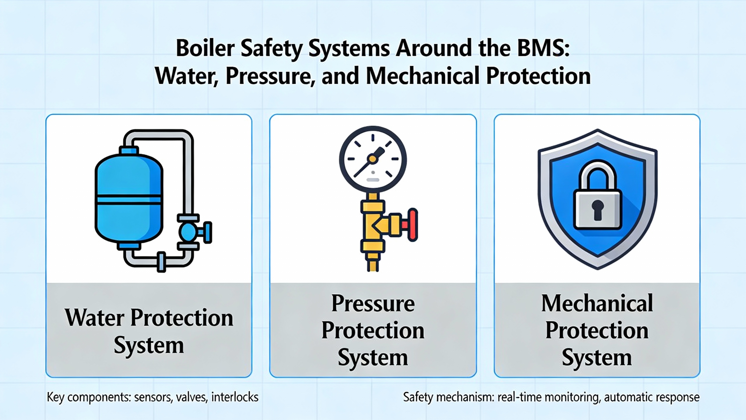
Boiler Safety Systems Around the BMS: Water, Pressure, and Mechanical Protection
A safe BMS cannot rescue a boiler that is mechanically unsafe. Raadman Burner and Atlas Copco both highlight how mechanical and electronic safety systems must work together.
Mechanical safety components such as temperature and pressure indicators, sight glasses, level controllers, and safety valves are the first line of defense. Level controls work with feedwater pumps and burner permissives so that low water levels shut down firing and prevent tube overheating. Safety valves relieve overpressure by venting steam or hot water before the pressure vessel reaches its design limit. Atlas Copco reminds us that when water flashes to steam it expands roughly fourteen hundred times in volume, so an uncontrolled release of high-pressure water or steam can be catastrophic.
Electronic safety elements include pressure switches, transmitters, and the burner controller itself. Advanced controllers, such as SIL-rated micro-modulating systems noted by Raadman, can combine burner and boiler control in one platform while still meeting international safety standards. Still, the BMS portion must retain a conservative, trip-focused design philosophy.
Water quality and internal protection also influence burner safety. The AquaPhoenix guide on scaling and corrosion explains that even about 0.04 inch of hard scale on tube surfaces can raise fuel consumption by approximately five to eight percent and create hot spots that lead to tube failures. Corrosion driven by dissolved oxygen and low pH causes pitting and thinning, which can turn into leaks or ruptures under pressure. Boiler safety operation manuals from industrial vendors point out that tube bursts and furnace explosions are frequently traced back to water-treatment lapses and incorrect responses to alarms, not to random metal failures.
In practical terms, this means the BMS must be part of a broader boiler safety regime. You can have a SIL3 shutdown loop, but if your low-water cutouts are bypassed or your safety valves have not been tested in years, your risk profile is still unacceptable.
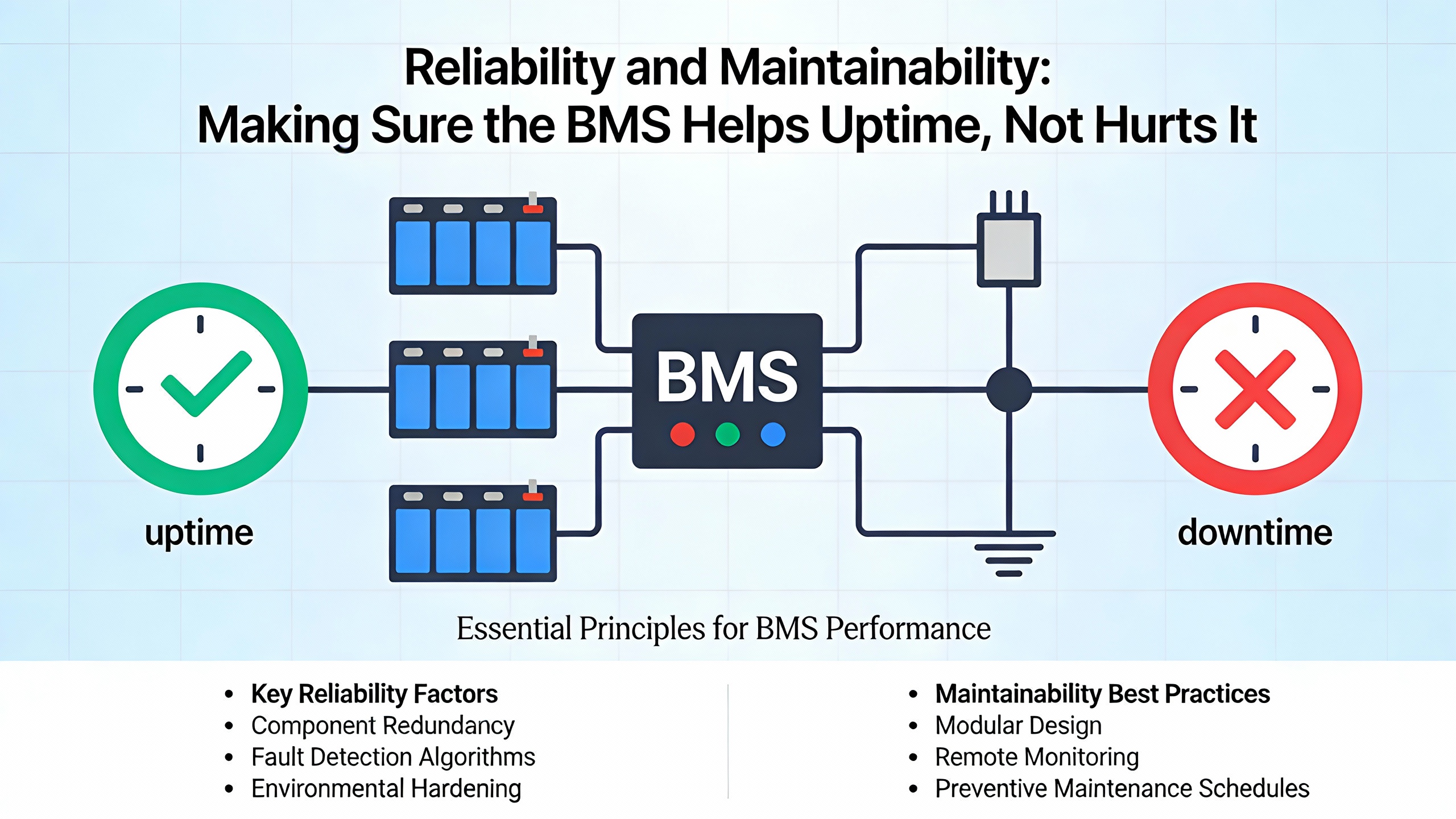
Reliability and Maintainability: Making Sure the BMS Helps Uptime, Not Hurts It
From a reliability engineering perspective, a burner management system can either be your best ally or your biggest source of spurious trips. Turbine Logic highlights early warning signs of BMS issues: frequent alarms, recurring flame failures, unstable temperatures and pressures, and unusual behavior when load changes. Many of these symptoms trace back to instrumentation problems, improper calibration, or age-related deterioration in sensors and valves.
Several sources converge on the idea that field devices drive most reliability problems, not the logic solver. The ISA article on BMS design and the SIL study of shutoff valves both show how the average probability of failure on demand is dominated by the actuator chain, especially main fuel shutoff valves. To improve real-world availability without compromising safety, you should focus on:
Selecting appropriately rated devices. All field devices on the fuel train and combustion air path must be rated for their service and installed according to safety guidelines. Recent safety valves with partial-stroke testing allow you to verify that they will close on demand, which materially improves both safety assurance and reliability.
Matching flame detectors to combustion. Flame scanners must be suited to the fuel mix, flame shape, and furnace geometry. If you change fuels or add firing modes, revisit detector selection. Applying a detector optimized for one set of spectral characteristics to another can cause either missed flame conditions or nuisance trips.
Using diagnostic-friendly devices. The ISA guidance notes that modular, maintenance-friendly equipment, such as top-entry gas regulators that can be cleaned in place, reduces downtime when contaminants cause sticking or drift. In my experience, devices that can be serviced without disturbing process piping and wiring shorten outages and reduce the temptation to defer repairs.
Providing clear operator interfaces and ŌĆ£first-outŌĆØ indications. When a fired unit trips, operators must quickly know which permissive failed first. BMS controllers that capture and display the initial cause of trip, as described in the Research Dive article, dramatically reduce troubleshooting time and restore confidence. Lamp test functions, clear HMI mimics, and explicit text messages matter more than many designers realize.
A simple example illustrates the payoff. Imagine a three-burner industrial boiler that trips three times in one week during peak production. Each time, operators see a generic ŌĆ£flame failureŌĆØ message and spend an hour checking pilots, fuel pressure, and dampers. The real cause turns out to be a marginal stack temperature detector that occasionally spikes high. If the BMS had logged and annunciated ŌĆ£High stack temperatureŌĆØ as the first-out condition, the plant could have replaced the detector after the first trip and saved several hours of downtime.
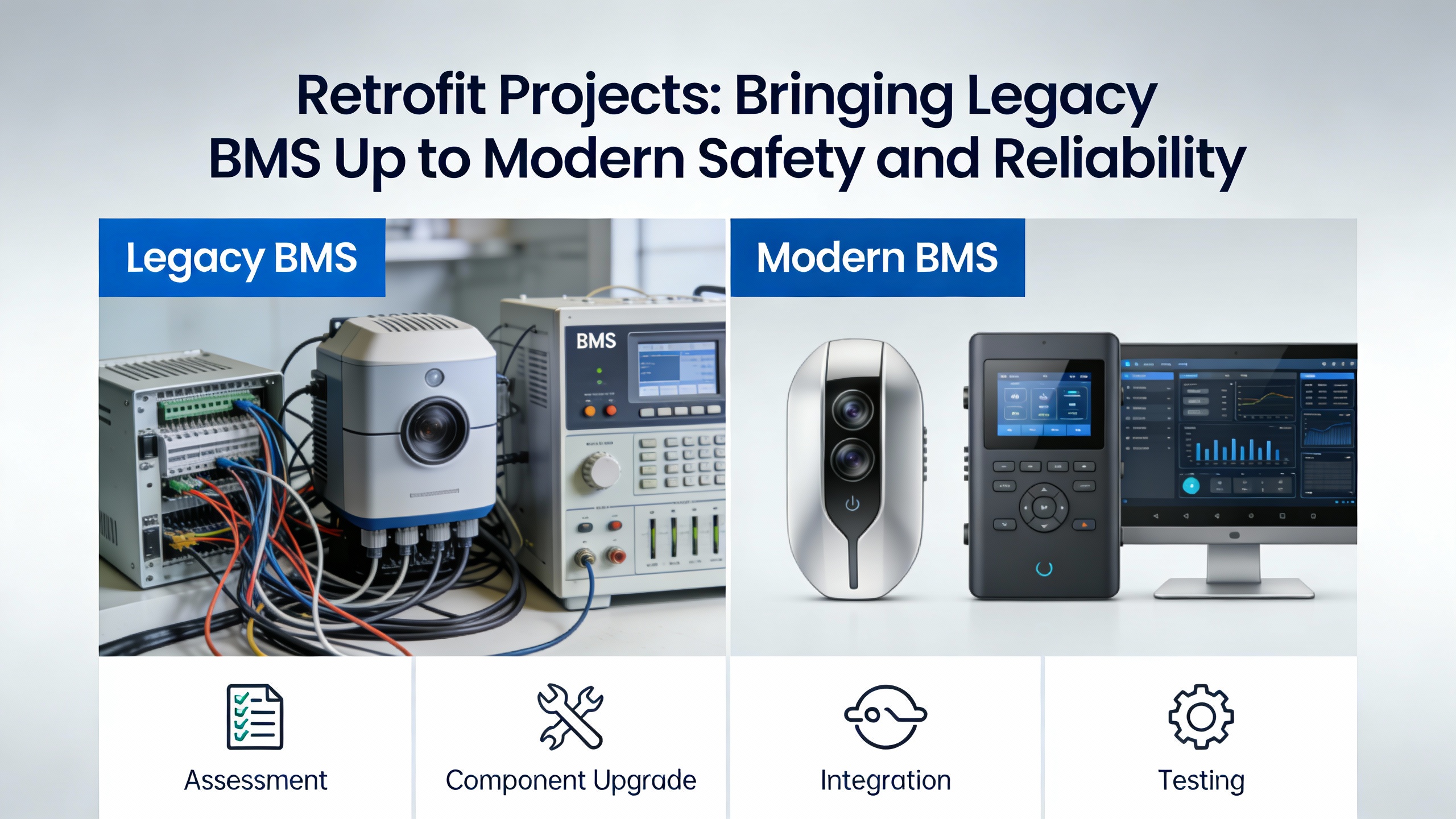
Retrofit Projects: Bringing Legacy BMS Up to Modern Safety and Reliability
Many plants are running on burner management systems that are twenty or thirty years old. ECS and other integrators describe retrofit projects not as simple control-panel swaps, but as strategic safety and reliability upgrades.
A well-run retrofit begins with a detailed assessment. This includes an inventory of current BMS hardware, wiring, interlocks, and flame safeguard devices, and a comparison against NFPA 85 or 86, as well as any applicable gas codes. Common gaps include lack of hardwired master fuel trip, inadequate purge logic, obsolete flame scanners, and no independent proof testing of valves.
Custom engineering then tailors the new system to the specific boiler, fuels, plant layout, and regulatory requirements. Typical elements include replacing legacy relay logic or outdated flame relays with a modern PLC or safety PLC platform, upgrading fuel shutoff valves and leak detection, modernizing instrumentation, and cleaning up wiring diagrams and causeŌĆæandŌĆæeffect matrices.
A key reliability lesson from retrofit case histories is the value of factory acceptance testing. Integrators such as ECS and Emerson emphasize fully testing control panels, logic, and I/O simulation in the shop before shipment. That allows purge cycles, flame detection, trips, and alarms to be verified and debugged while the plant is still running, compressing the onsite commissioning window.
Once installed, commissioning includes thorough I/O checks, live burner sequence testing, and operator training. Post-startup, plants should insist on complete documentation, including as-built drawings, logic diagrams, safety requirement specifications, and software backups. That documentation is not only vital for future troubleshooting; it also supports functional safety audits and supports consistent maintenance.
From a power-system perspective, a BMS retrofit is often the right moment to upgrade power protection as well. Integrating proper UPS-backed control power for the BMS logic solver and critical field circuits, along with surge protection and clear segregation from non-critical loads, significantly improves the odds that the safety system will do its job during electrical disturbances.
Practical Example: Combining Combustion, Safety, and Water Treatment
To see how these elements come together, consider an industrial plant with a pair of 150,000 lb/hr watertube boilers that feed a steam turbine generator and process users. The boilers fire natural gas with distillate oil backup. Originally they were equipped with relay-based BMS panels and minimal diagnostics.
A modernization project replaces the relay logic with a SIL3 safety PLC, while combustion control moves to the plant DCS. The new BMS enforces NFPA 85-compliant purge and ignition sequences, uses dual flame scanners per burner, and introduces a dedicated high-stack-temperature safety function implemented in approved safety hardware. Main fuel shutoff valves are upgraded to SIL2-certified units with partial stroke testing, and pressure transmitters on the fuel trains and air flow paths are also SIL-rated.
Water treatment is overhauled along lines similar to those suggested by AquaPhoenix and boiler safety manuals: softening and demineralization are improved, dissolved oxygen is controlled with scavengers, and a proactive blowdown program is instituted. Instrumentation upgrades include reliable low-water cutouts and modern level transmitters.
After commissioning and a year of operation, the plant records fewer nuisance trips, a measurable reduction in fuel consumption due to cleaner heat-transfer surfaces and well-tuned airŌĆōfuel ratio, and higher confidence in trip events because operators can see precise first-out causes. Functional safety assessments show a shutdown PFDavg consistent with the target SIL3 level for main fuel isolation. In turn, the siteŌĆÖs electrical reliability improves, because unexpected boiler trips and associated steam turbine upsets become rare.
Short FAQ
How is a burner management system different from combustion control? The BMS is a safety system that decides whether it is safe to admit fuel and maintain a flame, supervising purge, ignition, flame detection, and emergency shutdown. Combustion control handles how much fuel and air to supply to meet load efficiently. Best practice, reflected in NFPA 85 and industry guidance from aeSolutions and Kolmetz, is to keep these roles independent so that efficiency adjustments cannot compromise safety.
Do I need a safety PLC and SIL-rated devices for every boiler? Not necessarily. Flame safeguard relays and carefully designed general-purpose PLC solutions can meet code and provide adequate safety for smaller, less critical units, provided you rigorously follow NFPA and manufacturer requirements. However, for high-consequence boilers, especially those serving power generation or major process plants, the combination of a safety PLC and SIL-rated valves and sensors, as illustrated in the SIL study of BMS shutoff valves, makes the safety and reliability case far stronger and often simplifies compliance over the life of the system.
What are the biggest reliability weak points in a BMS? Studies and field experience consistently point to field devices rather than the logic solver. Main fuel shutoff valves with poor test coverage and non-specialized flame detectors are common sources of dangerous failures and nuisance trips. Articles from ISA, Research Dive, and the SIL analysis all emphasize the importance of selecting appropriate, rated field instruments, providing regular proof testing, and using diagnostic features such as partial-stroke testing and first-out trip indication.
In industrial power and boiler plants, safe combustion is not negotiable, but neither is uptime. A well-conceived burner management system, grounded in NFPA and API standards, validated with SIL-based methods, equipped with reliable field devices, and supported by robust power protection, transforms the boiler from a latent hazard into a dependable energy asset. Designing and maintaining that layer with care is one of the most leveraged investments you can make in both safety and reliability.
References
- https://www.academia.edu/125168321/Safety_Integrity_Level_of_Shut_Off_Valve_in_a_Burner_Management_System
- https://docs.nrel.gov/docs/fy04osti/35863.pdf
- https://oaktrust.library.tamu.edu/bitstreams/f671d8f0-fe39-4a21-bd89-cb5f148a8385/download
- https://ehs.usc.edu/research/lab/laboratory-burner-safety/
- https://www.dli.mn.gov/sites/default/files/pdf/boiler-safety.pdf
- https://digital.library.unt.edu/ark:/67531/metadc895558/m2/1/high_res_d/924683.pdf
- https://blog.isa.org/issues-considerations-design-burner-management-system
- https://www.epcbboiler.com/comprehensive-boiler-safety-operation-manual.html
- https://stanyanhill.com/burner-management.php
- https://www.aesolutions.com/post/understanding-how-burner-management-systems-work


 Videos
 News
News Applications


Leave Your Comment