Keeping a Bently Nevada 3500 rack healthy starts at the left side of the chassis, where the 3500/15 power supply modules quietly convert site power into clean, stable voltages for every monitor, relay, and interface in the system. When the rack goes dark, goes intermittent, or throws ambiguous alarms, the power path is the first place a reliability engineer should prove out. Drawing on the manufacturerŌĆÖs datasheets and maintenance manuals from Baker Hughes Bently Nevada, together with real-world lessons captured by industry distributors and field notes, this guide explains how the 3500/15 is built, what its indicators actually mean, and how to resolve the most common power supply problems without guesswork.
The 3500/15 in context
The 3500/15 is a half-height module installed in designated slots on the rackŌĆÖs left side. A rack may use one or two supplies in any mix of AC or DC variants. When two are installed, the lower slot serves as the primary and the upper slot as the backup. Either unit is capable of powering the entire rack, and if a second supply is present, removing or inserting a supply does not interrupt operation. This architecture, documented in the 3500 System Datasheet from Baker Hughes Bently Nevada, also clarifies a subtle but important behavior: switchover is essentially instantaneous, and the ŌĆ£Supply OKŌĆØ LED on each module is your first, fastest diagnostic tool.
Power to the 3500/15 enters through a matching Power Input Module (PIM). The PIM provides the line interface appropriate to the chosen supply type and houses the primary fuse protection. The PIM and supply must be of the same family; for example, a Universal AC supply must be paired with a Universal AC PIM. This like-with-like pairing is not a formality. Manufacturer guidance highlights that Universal AC and its PIM are not backward-compatible with legacy 3500 AC supplies, and the same is true of newer DC supplies versus legacy DC variants.
Specifications that matter in troubleshooting
What you measure and what the hardware is designed to do need to line up. The tables below summarize the input types, ranges, and full-rack current draw limits frequently referenced during triage and circuit sizing, consolidated from the Baker Hughes Bently Nevada datasheet and field notes from NexAuto Technology.
| Input type | Nominal range at the PIM | Max fullŌĆærack current draw |
| Universal AC | 85 to 264 Vac rms | Up to 2.8 A rms |
| High Voltage AC | 175 to 264 Vac rms | Up to 2.3 A rms |
| Low Voltage AC | 85 to 132 Vac rms | Up to 4.5 A rms |
| High Voltage DC | 88 to 140 Vdc | Up to 2.5 A |
| Low Voltage DC | 20 to 30 Vdc | Up to 10.0 A |
When the power supply is operating in hazardous areas, Bently NevadaŌĆÖs datasheet lists broad certifications and environmental bounds you should verify before service and whenever you plan an upgrade.
| Compliance or rating | Summary of claim (publisher: Baker Hughes Bently Nevada) |
| FCC Part 15 | Operates without causing harmful interference and accepts interference |
| EMC (EU) | EN 61000ŌĆæ6ŌĆæ2 industrial immunity; EN 61000ŌĆæ6ŌĆæ4 industrial emissions |
| Low Voltage Directive (EU) | EN 61010ŌĆæ1 electrical safety |
| RoHS (EU) | Directive 2011/65/EU substance restrictions |
| Maritime | DNV GL and ABS classifications |
| Hazardous areas (cNRTLus) | Class I, Zone 2 and Class I, Division 2 approvals, temperature class T4 |
| ATEX/IECEx | II 3 G with T4 at ambient ŌłÆ4┬░F to 149┬░F, per installation drawings 149243/149244 |
If you are verifying a physical module on the bench or confirming installation constraints, the typical envelope is about 4.75 in by 2.0 in by 9.9 in and an installed mass around 3.06 lb, which matches the datasheet values for the power supply and its input module family.
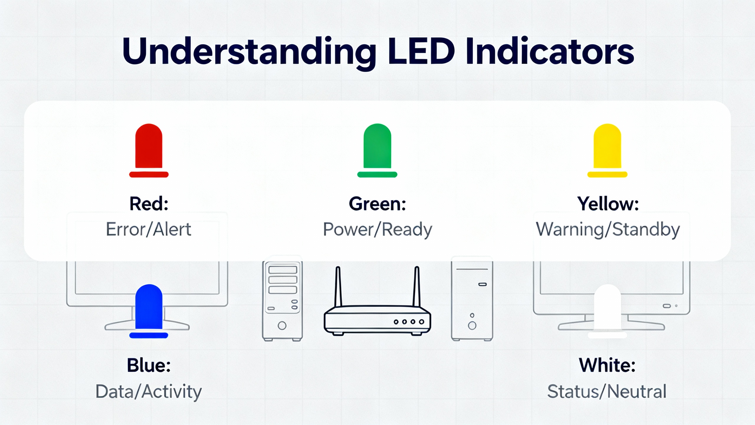
What the LEDs are actually telling you
LEDs on the supply and adjacent modules are not decorations; they are structured diagnostics. Vendors such as Ubest Automation emphasize that the combination of AC OK and DC OK on the supply indicates both the presence of input power and the health of the internal conversion stages, while the rackŌĆæwide ŌĆ£Supply OKŌĆØ LED is the fastest proxy for output health under load.
| Indicator | Normal meaning | When off or red | Immediate action |
| Supply OK (front) | Output rails are within tolerance | Output out of tolerance or module fault | Verify input at the PIM; confirm PIMŌĆōsupply family match; check PIM fuse |
| AC OK (supply) | AC input present to the PIM | No or incorrect AC input | Confirm feeder voltage and wiring at the PIM terminals |
| DC OK (supply) | Internal DC output is healthy | Output missing or out of spec | Suspect blown PIM fuse, failed supply, or severe overload |
| Monitor OK (rack cards) | Channel and module selfŌĆæchecks are normal | Blinking for bypass; red FAIL for hardware fault | Investigate module seating; review configuration; swap test with knownŌĆægood card |
Short, deliberate checks against this table, followed by the moduleŌĆæspecific manual if needed, allow you to prove or clear the power path in minutes.
A proven method when the Universal AC ŌĆ£OKŌĆØ LED is off
The operation and maintenance manual describes a straightforward sequence that resolves a surprising amount of downtime. Start at the PIM and the label on the module, not in the configuration software. Confirm the feeder voltage reaching the PIM is within the Universal AC range, then confirm the installed PIM type matches the supply family. If those prove correct, remove a rear screw and slide the PIMŌĆÖs sheetŌĆæmetal cover to expose the ceramic fuse. Because the fuse body is opaque, measure continuity rather than looking for a broken filament. The specification is a fastŌĆæblow ceramic fuse, 5 A at 250 V, size 6.3 by 32 mm. A measured resistance greater than about 1 ohm indicates an open fuse that must be replaced. The manual cites manufacturer part references, including the Bently Nevada spare fuse part number 120M3877 and equivalent ceramic fastŌĆæblow types in the same rating. After replacing the fuse, reŌĆæverify the AC and DC OK indicators. If the LED remains dark after these steps, install a knownŌĆægood Universal AC power supply. If the LED then illuminates, the original supply is faulty. If the problem persists with a knownŌĆægood supply, the PIM itself may be damaged and should be replaced.
Safety comes first, even with the rack powered down
Power supplies and relay contacts can hold energy after you pull mains or DC. The manufacturerŌĆÖs warning language is unambiguous: multiple sources may be present, and hazardous voltages may persist on AC and DC power supplies for several minutes after removal. Always remove all sources, use proper isolation techniques, and wait several minutes before handling. Where Class I, Division 2 or Zone 2 approvals matter, follow the referenced installation drawings and siteŌĆæspecific procedures so that you maintain the T4 temperature class in service.
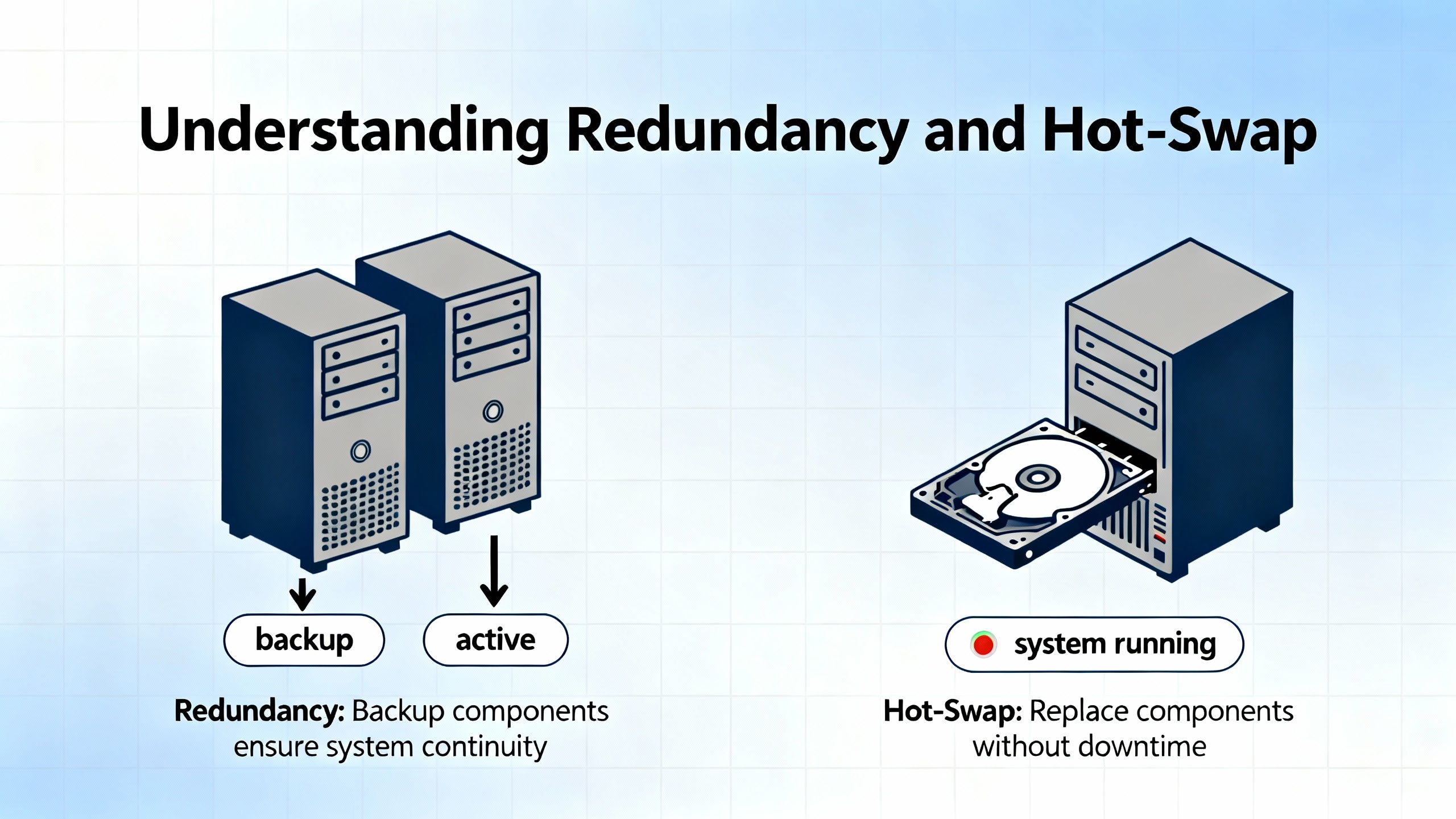
Redundancy and hotŌĆæswap without surprises
Redundancy cuts risk, but only when you understand the switchover rules. With two supplies installed, the lowerŌĆæslot unit is primary and the upperŌĆæslot unit is backup. Instantaneous transfer minimizes impact, but never assume switchover is silent. Verify the ŌĆ£Supply OKŌĆØ LED and DC OK indicator on the remaining unit when you pull the primary. If a supply fails, the rack can continue to run indefinitely on the surviving unit within the current draw limits shown earlier. When you reseat or replace a supply, confirm that the OK LED behavior matches expectations and that no nuisance rack alarms remain latched.
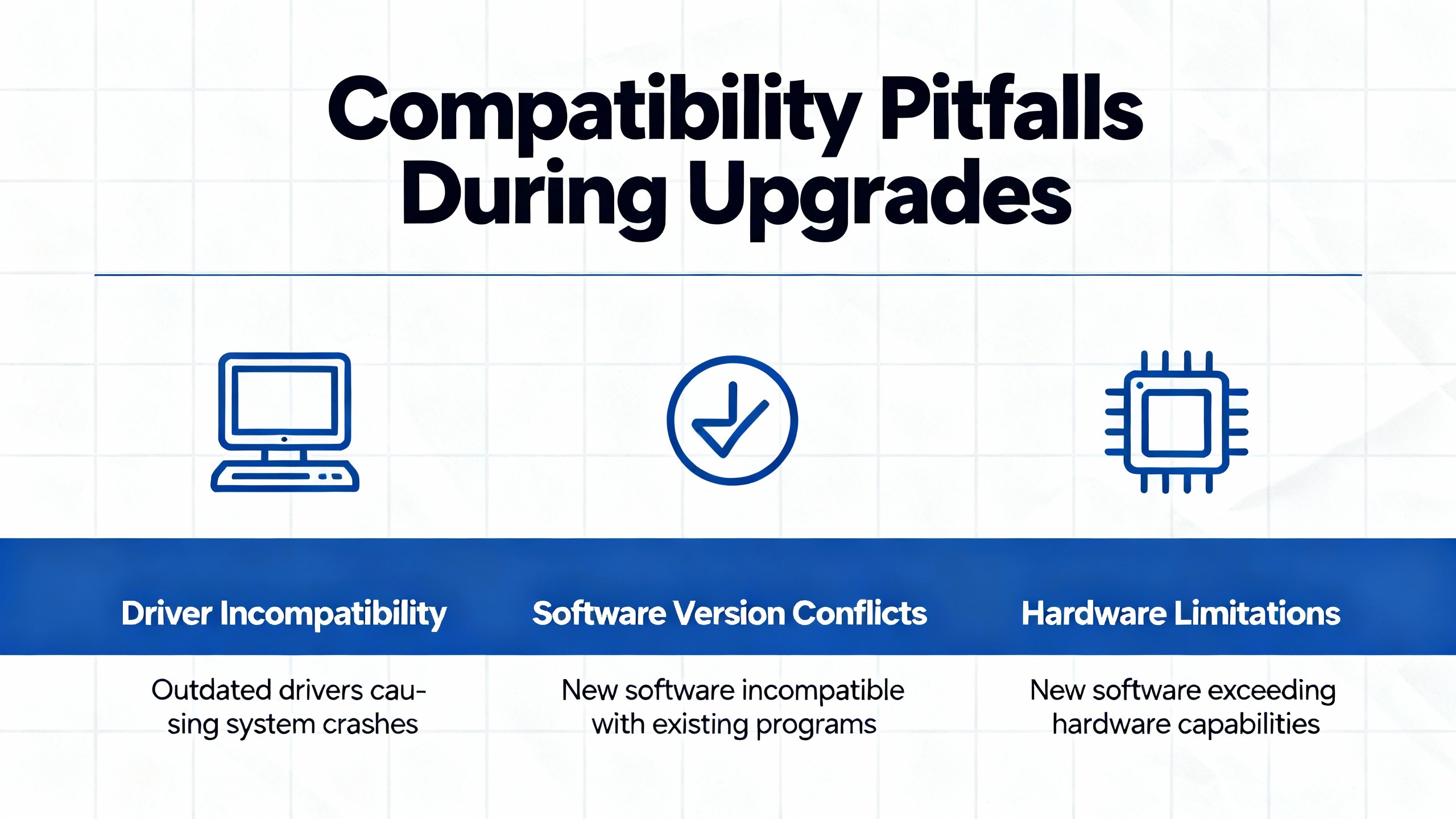
Compatibility pitfalls during upgrades
Universal AC, High Voltage DC, and Low Voltage DC variants in todayŌĆÖs 3500/15 lineup use matching PIMs that are not compatible with legacy 3500 AC and DC PIMs. A powerŌĆæup with a mismatched pair often looks like an immediate rack failure with a dark OK LED and a good AC OK indicator, which tends to provoke unproductive module swapping. Before ordering, decode the 3500/15 string correctly and ensure it reflects the PIM and supply types for both top and bottom slots. The RMS DCS ordering guide shows the AA, BB, and CC fields, where the first two denote supply types by slot and the last field denotes agency approvals. Typical spare part numbers such as 125840ŌĆæ01 for a High Voltage AC PIM, 125840ŌĆæ02 for a Low Voltage AC PIM, 133292ŌĆæ01 for a Low Voltage DC supply, and 133300ŌĆæ01 for a Low Voltage DC PIM help inventory teams order correctly and help troubleshooters confirm what is in hand.
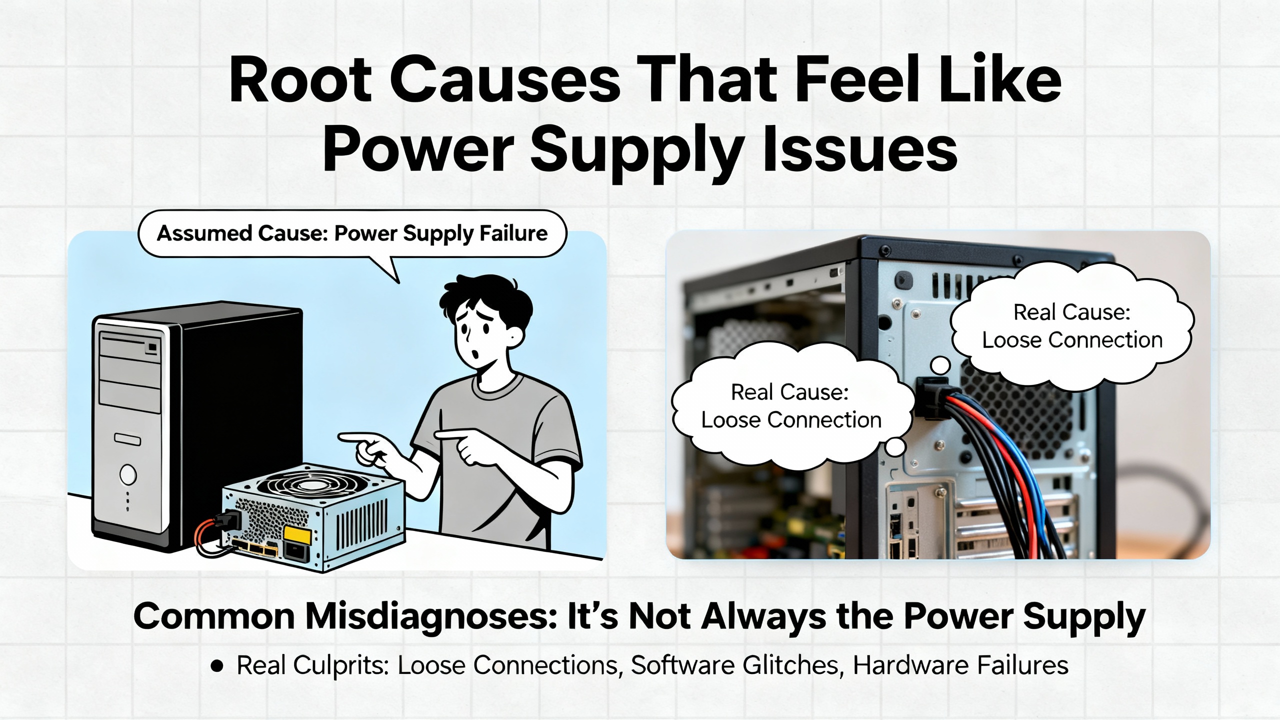
Root causes that are not the power supplyŌĆöbut feel like it
Power quality and distribution decisions ripple into monitoring reliability. Field guidance from Ubest Automation on 3500 systems suggests working through a triage order that starts with the supply indicators, then verifies communications, sensors, and modules. If Modbus or Ethernet data is missing, do not overlook the TDI (Transient Data Interface) status or upstream switches and cabling. Ground loops can masquerade as power instability by injecting noise into vibration channels and causing secondary alarms. A measured, stepwise approachŌĆöpower first, communications next, then sensors, module swap tests, grounding, and configurationŌĆöusually converges faster than shotgun part replacement.
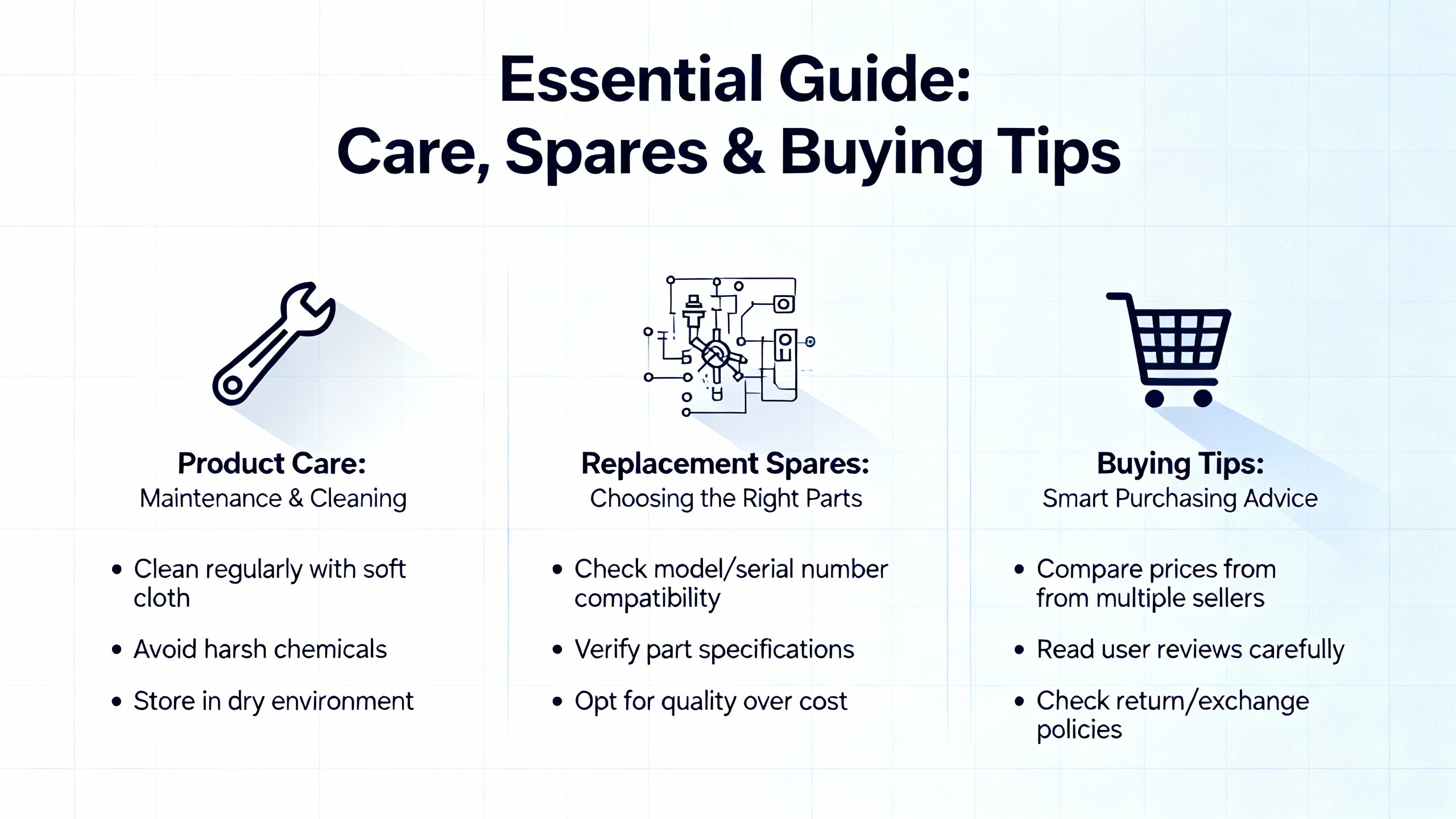
Care, spares, and buying tips
A power supply failure should be a planned swap, not a plant event. Maintaining a small kit of proven spares and consumables pays for itself the first time you need it. Keep a matched spare PIM and 3500/15 supply of the family you run, and stock the fastŌĆæblow ceramic fuses in the 5 A, 6.3 by 32 mm size used in the PIM. When buying new or replacement modules, verify that the label and ordering code match your installed base, and that agency approvals on the nameplate meet your site classification. The Approvals Quick Reference Guide cited in the datasheet makes this fast. For critical assets, consider feeding redundant supplies from independent circuits to avoid a singleŌĆæpoint feeder failure. After any power work, back up the rack configuration and perform a quick LED and alarm check before returning highŌĆærisk machinery to automatic service.
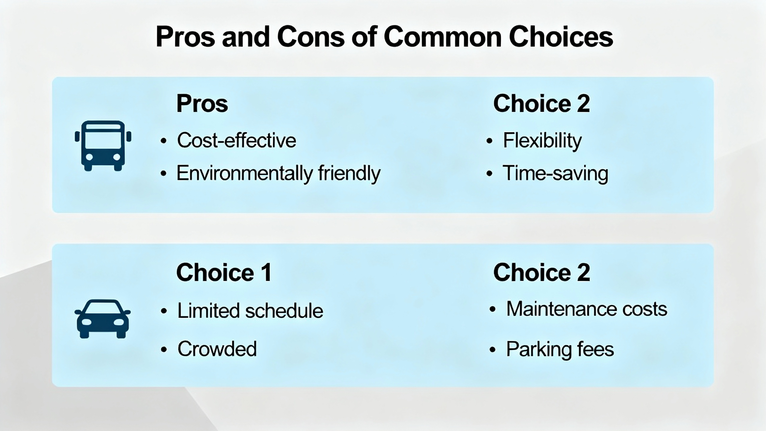
Pros and cons of common choices
Choosing between AC and DC input types often comes down to site power topology. Universal AC simplifies global spares and allows a broad feeder range, while a 24 Vdc Low Voltage DC configuration offers tight integration with plant UPS systems at the cost of higher rack current draw, which must be accommodated in circuit sizing. SingleŌĆæsupply racks minimize capital cost and footprint, but dual supplies materially improve availability and allow hotŌĆæswap maintenance if the backup is installed. Legacy compatibility is the hidden downside of otherwise attractive upgrades: Universal AC families are not crossŌĆæcompatible with older 3500 AC PIMs, and the same holds for DC variants, so mixing generations indiscriminately creates intermittent failures that are hard to diagnose.
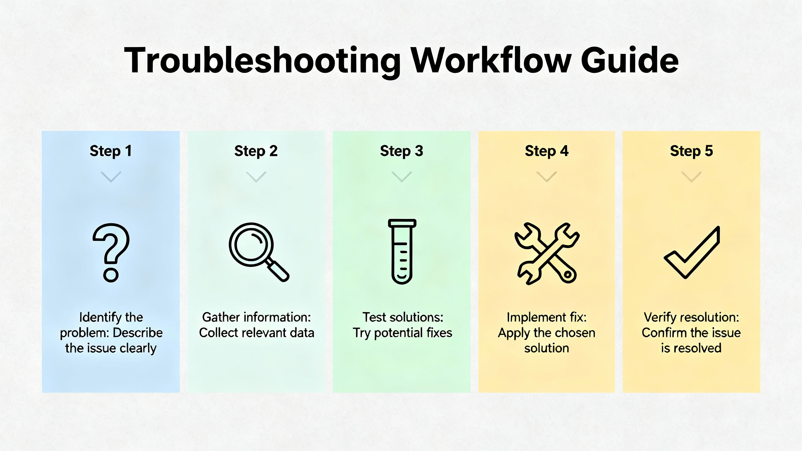
A concise, stepwise troubleshooting workflow
If a 3500 rack shows loss of power or intermittent resets, begin with a visual and indicator check. Confirm that AC OK and DC OK on the supply are green, and that ŌĆ£Supply OKŌĆØ is illuminated. When the Universal AC ŌĆ£OKŌĆØ LED is off, verify feeder voltage at the PIM terminals, confirm the PIM class matches the supply label, and measure the PIM fuse continuity using a meter rather than a visual inspection. Replace the fuse with a ceramic fastŌĆæblow 5 A, 6.3 by 32 mm part if it is open. If the LED remains off, install a knownŌĆægood supply. When AC OK is off, check the site feeder, protective devices, and the PIM terminal wiring. During these checks, ensure residual energy has been allowed to decay and all sources are isolated. When LEDs indicate normal and a rackŌĆæwide issue persists, continue with the discipline used in vibration and protection triage: check the TDI communications indicators, review recent configuration changes, and examine grounding and module seating before concluding that a supply problem exists.
Selecting and sizing with data rather than rules of thumb
The current draw of a full 3500 rack depends on what you have installed. As a planning baseline, Universal AC and High Voltage DC variants for a fully loaded rack are generally specified at a few amperes, while Low Voltage DC can approach 10 A. Given these values from Baker Hughes Bently Nevada and field articles, design site circuits and UPS links to handle the worstŌĆæcase draw with margin. Doing so avoids nuisance undervoltage conditions that leave the rack running but vulnerable to data corruption or silent resets. The thermal environment matters as well. HazardousŌĆæarea approvals for T4 rely on ambient not exceeding about 149┬░F, so confirm your enclosures, solar loading, and HVAC setpoints keep the supplies within their temperature envelope.

A short case in point
A plant reported an otherwise normal rack with a dark ŌĆ£Supply OKŌĆØ LED after an outage on a hot day. The AC OK lamp was green, and the DC OK lamp was off. The technician verified the feeder at the PIM was within the universal range and then opened the PIM to meter the fuse. The ceramic 5 A fuse read open and was replaced with a spare from the kit. DC OK and ŌĆ£Supply OKŌĆØ came up immediately, and the rack resumed service. The engineer then verified redundant supply operation and updated the spares list to replenish fuses. No monitors were swapped, and no configuration was touched. The outcome hinged on knowing where the fuse lives and using a meter rather than a flashlight to determine its condition, exactly as described in the operation and maintenance manual.
Frequently asked questions
What is the difference between the PIM and the power supply module in a 3500 rack? The PIM is the power entry module that interfaces to line or DC feed and houses the primary fuse; the 3500/15 converts that input into the regulated voltages used by the rack. They must be from the same family, such as Universal AC with a Universal AC PIM, to function properly.
Can I hotŌĆæswap a failed supply without shutting down the rack? Yes, if a second supply is installed and healthy. With dual supplies, the rack remains powered when you remove one module. You should still confirm indicators and alarms before and after the swap, and you should follow the manufacturerŌĆÖs guidance for waiting times because stored energy can persist on removed modules for several minutes.
What does temperature class T4 actually mean for my installation? T4 correlates with a maximum surface temperature of about 135┬░C on certified equipment. The Bently Nevada datasheet ties this to an ambient of roughly ŌłÆ4┬░F to 149┬░F when installed per the referenced drawings. Staying within that ambient window helps preserve approvals in Class I, Division 2 or Zone 2 sites.
Can I replace a legacy AC supply with a Universal AC supply to simplify spares? Only if you replace the PIM with the matching Universal AC PIM at the same time. The manufacturer notes that Universal AC families are not backward-compatible with legacy AC PIMs. A mixed pair looks like a failed rack even when both parts are individually functional.
How do I decide between AC and DC variants? Use what your site can support reliably. Universal AC broadens feeder options and simplifies global spares. Low Voltage DC integrates well with plant UPS systems and DC distribution but may draw up to 10 A for a full rack, which has implications for wire sizing and protective devices.
What is the fastest way to prove whether the supply or the PIM is bad? Start with indicators, then verify the feeder at the PIM, confirm PIMŌĆōsupply family match, and meter the PIM fuse. If a knownŌĆægood fuse and a correct PIM still yield a dark ŌĆ£Supply OK,ŌĆØ install a knownŌĆægood supply to see whether the fault follows the supply. If the fault persists with a knownŌĆægood supply, suspect the PIM.
Takeaway
Power anomalies in a 3500 rack do not have to be mysteries. The supply architecture is simple, the LED indicators are meaningful, and the most common failure in the Universal AC pathŌĆöa blown ceramic fuse in the PIMŌĆöis easy to prove with a meter. The essentials are consistent: verify the feeder at the PIM, ensure the PIM and supply are from the same family, use the datasheetŌĆÖs current limits to size circuits and UPS links, respect residual voltages during service, and exploit redundancy when it is available. Manufacturer sources such as the Baker Hughes Bently Nevada 3500/15 datasheet and Operation and Maintenance Manual, together with ordering and part details from distributors like RMS DCS and practical LED interpretation notes from Ubest Automation and NexAuto Technology, provide enough signal to resolve power supply problems methodically and keep racks protecting critical machinery without drama.
References
- https://www.academia.edu/43778168/3500_System_Product_Datasheet_Bently_Nevada_Asset_Condition_Monitoring_Description
- https://borgoltz.aoe.vt.edu/aoe3054/manual/expt6/3300xl_8mm_proximity_transducer_141194aa.pdf
- https://digitalcommons.calpoly.edu/context/theses/article/4356/viewcontent/THEORETICAL_AND_EXPERIMENTAL_STUDY_OF_ACTIVE_MAGNETIC_BEARINGS_Rev3.pdf
- https://studylib.net/doc/27017185/bently-nevada-3500-proximitor
- https://actechparts.com/bently-nevada-3500-15-ac-dc-power-supply-complete-guide-3/
- https://www.plcdcspro.com/products/bently-nevada-3500-15-01-01-00-125840-02-low-voltage-power-supply
- https://www.powergearx.com/maximizing-uptime-the-essential-bently-nevada-3500-maintenance-checklist/
- https://www.rms-dcs.com/bently-nevada-350015-04-04-00-133292-01-low-voltage-dc-power-supply-module-product/
- https://www.artisantg.com/TestMeasurement/78116-1/GE-Bently-Nevada-3500-15-AC-Power-Supply-Module?srsltid=AfmBOorMzrNhWFOEoVAv2HGTMxdNkKouGk2guoP8brrkhMZKvOTnseck
- https://www.manualslib.com/manual/3467945/Ge-Bently-Nevada-3500-15-Series.html?page=3


 Videos
 News
News Applications


Leave Your Comment