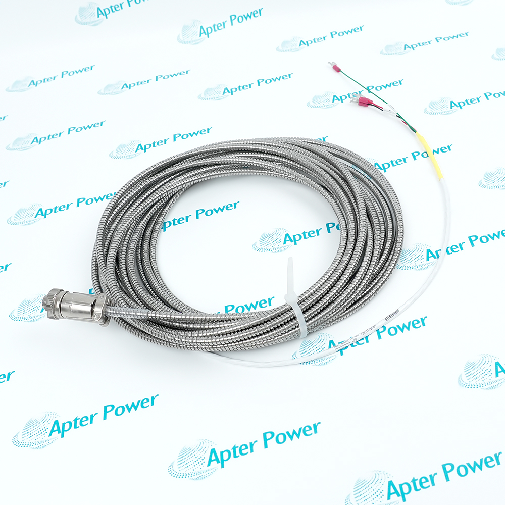
-
Match the complete marking
Include 16710-26 and the marking visible on the cable assembly. Keep the exact reference on your enquiry and quotation.
-
Check the offered item before ordering
Request available plug, terminal-lug and label photos. Have your maintenance team compare the offered 16710-26 with the installed accelerometer wiring and applicable Bently Nevada technical information.
Technical specifications for 16710-26
-
Manufacturer:Bently Nevada
-
Product Category:Machinery Monitoring Systems
-
Spare Part Number:16710-26
-
Weight:0.64 kg
-
Tariff Code:8537101190
-
Cable role:330400/330425 accelerometer interconnect
-
Ordered length:26 ft (7.92 m nominal)
-
Cable conductors:3, shielded
-
Conductor gauge:22 AWG (0.5 mm²)
-
External protection:Armored cable
-
Transducer-end interface:3-socket plug
-
Receiving-end interface:Terminal lugs
-
Length selection:AA in 1 ft (305 mm) increments
-
Allowed ordered length:3–99 ft (0.9–30 m)
-
Listed standard lengths:6, 8, 10, 12, 15, 17, 20, 25, 50, 99 ft
-
Length class:Permitted nonstandard ordered length
-
System context:330400 / 330425 accelerometers; verify connected receiving instrument
Information
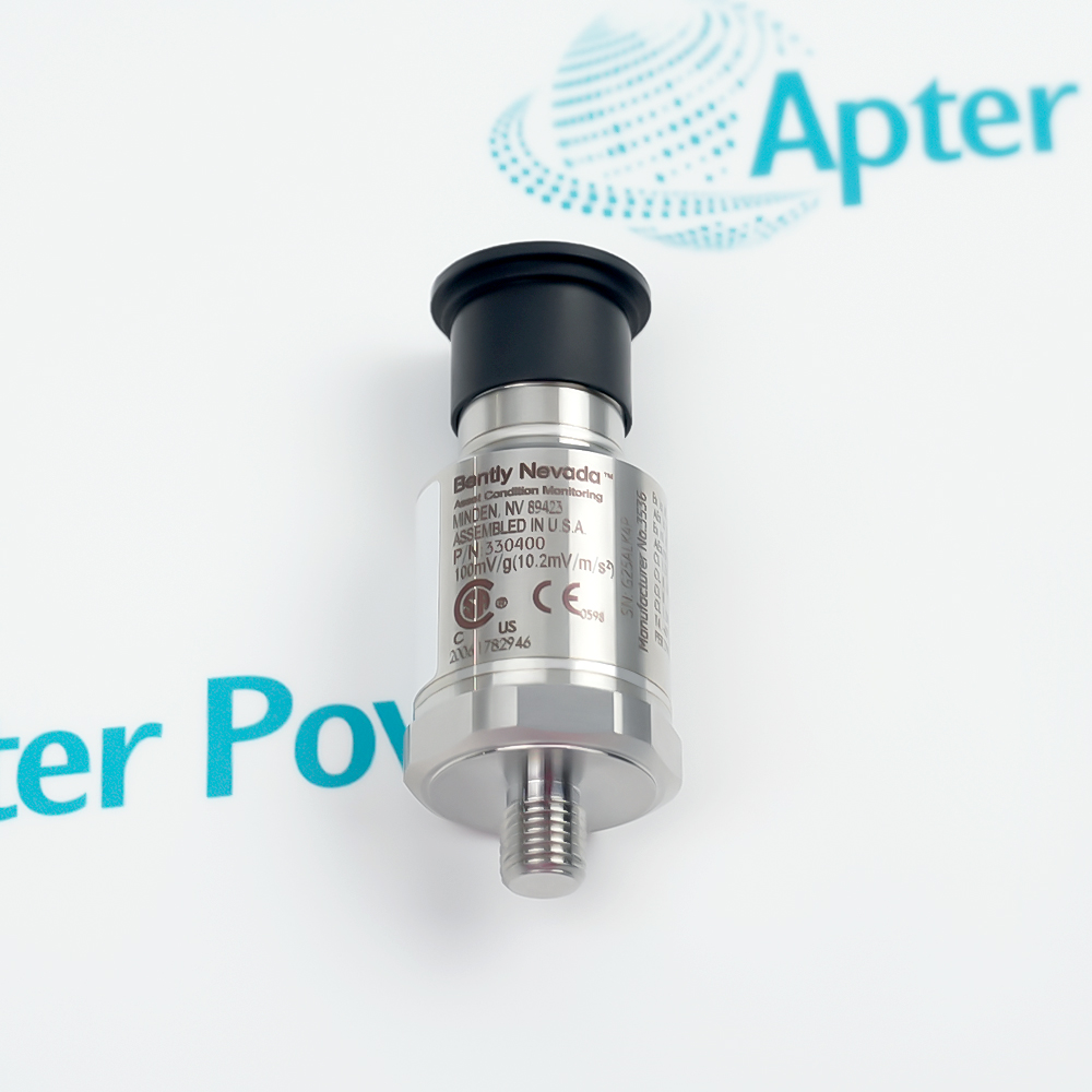
- Bently Nevada 16710-26 carries an accelerometer signal from the machine-mounted transducer toward the receiving monitoring circuit. The ordered cable is an interconnect, not the sensing element.
Connection path: 3-socket plug to terminal lugs
Order selection: 26 ft cable option
The 26 suffix selects 26 feet of ordered cable. This falls inside the manufacturer's 3–99 ft selectable range but is not one of the listed standard lengths. Confirm the installed route, connector access and terminal location before assigning the cable to a channel.
At replacement, trace the three conductors and shield against the instrument drawing. Verify the plug mates with the actual accelerometer and the lug ends match the assigned input, common and shield points; do not infer conductor allocation from a cable photograph alone.
-
Bently Nevada 16710-26 technical reference
Original Bently Nevada 141638 Rev. AB excerpt - PDF, 5 pages, 230.2 KB. Covers 16710 cable construction, plug/lug ends and length selection. -
Bently Nevada 16710-26 installation planning guide
Prepared by Apter Power - PDF, 2 pages, 89.8 KB. Cable routing, terminal mapping, shield checks and channel acceptance.
Application boundary: The applications below require a correctly selected installed channel and actual machine drawing; the offered component does not establish complete-system performance.
-
330400 accelerometer channel
Use the armored lead as the defined interconnect between the 330400 sensor connector and the instrument terminal points. -
330425 accelerometer channel
Apply the same 16710 connector family when the installed 330425 arrangement calls for this cable; confirm the channel drawing. -
Routed field connection
Plan the ordered length against the complete machine route, service slack and entry hardware rather than straight-line distance. -
Service replacement
Compare connector keying, conductor landing and shield treatment with the removed lead before returning the channel to service.
Verify the 3-socket plug on the transducer end and terminal lugs at the receiving end before disconnecting the old cable.
Measure the installed routing path; do not rely on the nominal order length as proof of available installation slack.
Use the approved channel drawing for shield termination. Avoid undocumented changes that could introduce noise or ground loops.
Keep the route clear of sharp edges, moving equipment and cable crush points; inspect the jacket after securing the cable.
Do not assign 330400/330425 sensitivity, g range or frequency limits to the passive interconnect cable.
Inspect plug seating, lug torque and monitor input assignment, then check the measured signal with the installed transducer.
Alternative Names
Technical notes
Connection relationship: The 26 ft ordered interconnect joins a compatible 330400/330425 accelerometer to terminal wiring through a three-socket plug and lugs.
Installation boundary: Conductor landing, shield treatment and route protection follow the installed channel drawing; accelerometer sensing ratings are separate.
Technical reference: Bently Nevada 330400 and 330425 Accelerometers, 141638 Rev. AB. The cable ordering definition is the applicable evidence for this part.

FAQ View All FAQ
-
How should the terminal lugs of 16710-26 be assigned during a channel replacement?Use the controlled wiring drawing and trace each conductor from the three-socket plug before terminating the lugs. Preserve the original channel input, common and shield arrangement, then perform continuity and signal checks; cable color alone is not an approved assignment.
-
Can 16710-26 replace a 330400 accelerometer simply because the cable plugs into it?No. This part is the interconnect cable. Keep the installed transducer and channel identity separate; compare the complete sensor and monitoring arrangement before changing the sensing element.
-
What should an engineer do if the routed length of 16710-26 leaves too little service slack?Recheck the machine route, entry hardware and connector service loop. The manufacturer's order structure permits 1 ft increments within its stated range; choose a suitable ordered length rather than stressing the plug or lugs.
-
How can a suspected open conductor in 16710-26 be isolated?Disconnect both ends under the site's isolation procedure, then test each conductor and shield end-to-end with the channel drawing. Inspect the armor exit and plug strain relief, and avoid interpreting a reading through the connected accelerometer as cable-only continuity.
-
What installation condition can make 16710-26 introduce noise despite a good continuity test?An incorrect shield termination, damaged shield, loose lug or routing near a disturbance source can affect the receiving signal. Compare the terminations and route with the approved measurement drawing, then review the channel noise with the system operating.
-
Can 16710-26 be treated as proof that the connected 330425 channel meets its accelerometer specifications?No. The cable order defines the lead construction and ends. Check the connected accelerometer model, mounting, input and total wiring arrangement against the manufacturer's separate system data before accepting channel performance.
-
What should be inspected if the plug of 16710-26 loosens during machine service?Inspect mating contacts, plug seating, transducer connector condition and cable strain relief. Correct mechanical routing before reconnecting, then confirm the monitored signal and record the repair.
-
How should 16710-26 be accepted after replacing an existing interconnect?Compare both endpoint identities with the machine drawing, verify conductor continuity and shield landing, secure the armored route without crush points, and check that the monitor receives a stable response from the installed accelerometer.
Supporting new and legacy automation
-
Please try to be as accurate as possible with your search.
-
We can quote you on 1000s of specialist parts, even if they are not listed on our website.
-
We can't find any results for “”.
Related cases and sourcing guidance
View all case studiesYou May Also Like
Product Browsing History
-
Whatsapp: +86 18030235313
Send us a message. -
sales13@apterpower.com
Complete our online form. -
+86 18030235313
Speak to our team in your native language.