Speak to a sourcing specialist
sales13@apterpower.com

330104-00-25-50-02-CN

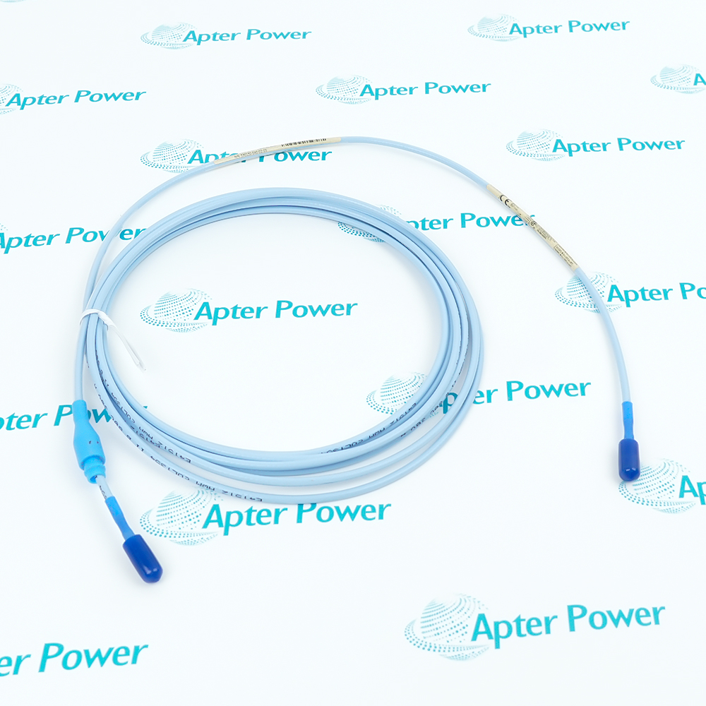
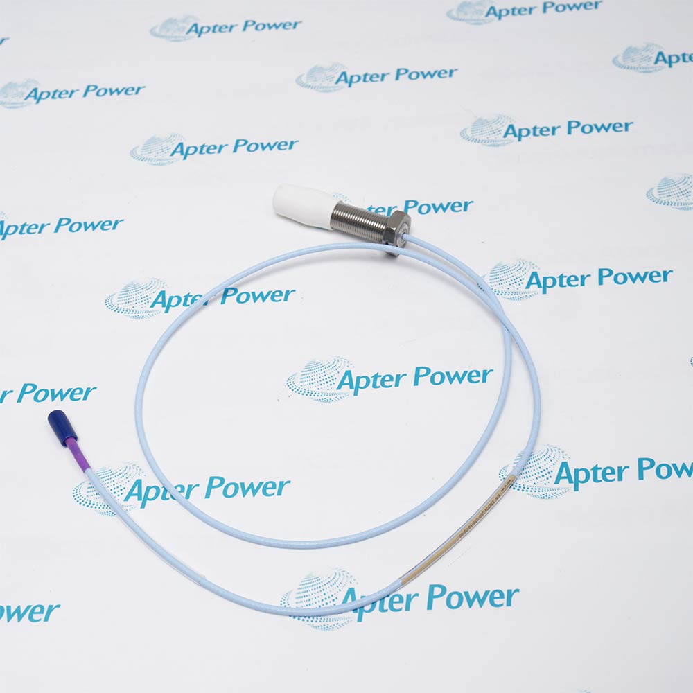
Armored Eddy-Current Proximity Probe
Product image is representative; revision or series may vary. Contact us to request a specific version.

Product Describe:

Bently Nevada 330104-00-25-50-02-CN senses the position and vibration of a conductive target through a matched 3300 XL 8 mm transducer system.
  • Manufacturer part number
    330104-00-25-50-02-CN
  • Shipping
    Swift global dispatch
  • Condition
    New, original product
  • Shipping size (est.)
    1.8cm x 1.5cm x 58.5cm
  • Country of Origin
    USA
Get a quick price for 330104-00-25-50-02-CN
E-mail *
Mobile *
Company
Content *
Quantity *
Upload (gif, jpg, jpeg, png, bmp, doc, docx, xls, xlsx, ppt, pdf, csv)
For more information on how your data is processed and stored by Apterpower please read our privacy policy

What happens after you enquire

  • 0

    Review your reference

    Send the complete 330104-00-25-50-02-CN reference, label photographs and required quantity, together with the installed system position.

  • 1

    Confirm the offer

    Review the offered 330104-00-25-50-02-CN execution, condition, included connection hardware and applicable documentation.

  • 2

    Arrange dispatch

    Confirm quantity, dispatch date and delivery details for 330104-00-25-50-02-CN in the quotation.

  • Match the complete marking

    Match the complete Bently Nevada 330104-00-25-50-02-CN marking, hardware execution and connection arrangement to the installed position before approving the order.

  • Check the offered item before ordering

    Request clear photographs of the offered 330104-00-25-50-02-CN and ask your maintenance team to compare its markings and interfaces with the installed equipment and applicable Bently Nevada instructions.

Technical specifications for 330104-00-25-50-02-CN

  • Manufacturer:
    Bently Nevada
  • Product Category:
    Machinery Monitoring Systems
  • Spare Part Number:
    330104-00-25-50-02-CN
  • Weight:
    0.14 kg
  • Tariff Code:
    8537101190
  • Sensing principle:
    Non-contact eddy current
  • Tip diameter:
    8 mm
  • Mounting thread:
    M10 x 1
  • Unthreaded section:
    0 mm
  • Case length:
    250 mm
  • Integral lead length:
    5.0 m
  • Lead construction:
    Armored standard coaxial cable
  • Connector:
    Miniature coaxial ClickLoc
  • Nominal system sensitivity:
    7.87 V/mm (200 mV/mil)
  • System linear range:
    2 mm (80 mils)
  • Standard calibration target:
    AISI 4140 steel

Information

Overview Downloads Applications / Compatibility Product Precautions
  • Bently Nevada 330104-00-25-50-02-CN uses its five-metre probe lead as the electrical-length element of a matching five-metre transducer arrangement.
Measurement role: Non-contact shaft position and vibration
Cable construction: Armored standard coaxial lead
Signal path: Matched probe, cable arrangement and Proximitor
The ordered mechanical arrangement has a 250 mm case with a 0 mm unthreaded section. Compare this geometry with the bracket and target position so that the probe can be secured without forcing its cable or shifting the intended sensing direction.

The five-metre probe lead is intended for a five-metre Proximitor system without an added extension. Cable reach must be planned around this calibrated arrangement; the supplied lead is not a general-purpose cable that can be cut to suit.

The conditioner output represents both static gap and dynamic target motion. Target material, mounting geometry and receiver configuration must remain within the intended measurement design. Armor protects the routed lead but does not replace proper support or connector protection.
Controller platform reference: 3300 XL 8 mm system. Use the applicable installation instructions and approved design.
The original technical excerpt supports 330104-00-25-50-02-CN configuration review. The separate Apter Power field guide organizes practical diagnostic checks. Installation topics include: check the 250 mm case and bracket relationship, identify the 5.0 m lead and matched conditioner, route armor and secure the coaxial connection.
Original manufacturer pages retain their technical context. Use the Apter Power guide with the applicable manufacturer instructions and approved installation design.
System and supply context: 330104-00-25-50-02-CN belongs to the 3300 XL 8 mm system installation described by the technical reference. Connected equipment and accessories must be included explicitly in the configured assembly.

Application scope: The following uses describe supported engineering roles; they do not establish interchangeability with another model or remove application-specific validation.
Prepare Bently Nevada 330104-00-25-50-02-CN for its configured installation using these checks.
Check the 250 mm case and bracket relationship

Record the probe position, target material, sensing direction and monitor channel before removal. Compare the 250 mm case and 0 mm unthreaded portion with the actual bracket and working space. Preserve the original operating gap and the accepted channel scaling so a mechanical replacement does not silently alter the measurement baseline.

Identify the 5.0 m lead and matched conditioner

Trace the 5.0 m integral lead to its conditioner and identify the complete calibrated arrangement. This probe is used with a five-metre Proximitor system without an extension cable. Keep the machine protection in its approved maintenance state while the channel is interrupted, and label the coaxial connections before disconnecting them.

Route armor and secure the coaxial connection

Inspect the probe tip, armored lead and connector for damage or contamination before installation. Route the armor with support that does not pull on the probe or coaxial connection. Secure the intended mounting position and protect the connector using the applicable installation method, then verify the gap again after locking the mechanical arrangement.

Verify gap response against the actual target

Use the matched chain and a suitable target to observe output at controlled gap positions within the intended operating region. Compare direction and sensitivity with the system requirements, allowing for target material and the receiving instrument. Keep any dynamic interpretation separate from a static electrical verification.

Prove monitor scaling and protection response

Restore the channel to the intended monitor and confirm scaling, normal gap indication and the configured protection response. Perform alarm or reference-pulse checks only under the approved controlled test method. Remove temporary stimuli and reconcile bypasses before returning the measurement to service, retaining the final probe and conditioner identities.

Keep the technical scope explicit

Probe configuration follows the metric ordering table; stated system performance requires a matched transducer chain and the specified target conditions.


Alternative Names

Bently Nevada 330104-00-25-50-02-CN

Technical notes

Configuration baseline: Keep the installed 3300 XL 8 mm system arrangement aligned with the complete 330104-00-25-50-02-CN reference and its assigned system role.

Acceptance boundary: Compare the electrical or communication response with the intended application outcome before releasing maintenance controls.

Technical reference: Bently Nevada 3300 XL 8 mm Proximity Transducer System, 141194 Rev. AN. Probe configuration follows the metric ordering table; stated system performance requires a matched transducer chain and the specified target conditions.

FAQ View All FAQ

  • Can a standard extension cable be added to the five-metre lead of 330104-00-25-50-02-CN?
    The five-metre probe is intended for a five-metre Proximitor system. Adding an extension changes the calibrated electrical length. Use the supported complete-chain arrangement rather than adding cable merely to obtain more reach.
  • Why is connector protection important when routing 330104-00-25-50-02-CN through a cabinet?
    The coaxial connection must remain clean and mechanically secure. Contamination or strain can introduce unstable readings. Plan the cable route and protection before installation, then inspect the connection after routing.
  • How should the long case of 330104-00-25-50-02-CN be supported during mounting?
    Use the intended threaded mounting arrangement without bending or forcing the probe into misalignment. Check the target relationship after the assembly is secured. Mechanical case length is not additional sensing range.
  • Can excess lead on 330104-00-25-50-02-CN be shortened to simplify routing?
    No. Shortening or splicing alters the calibrated cable assembly. Retain its supplied length and route the excess appropriately, preserving the approved bend and environmental conditions.
  • Why must 330104-00-25-50-02-CN be tested with the actual conductive target?
    System sensitivity depends on target material and geometry. Verify response over the intended operating gap with the installed or representative target. A calibration made against a different metal cannot automatically establish field accuracy.
  • What can make 330104-00-25-50-02-CN readings change when nearby wiring is moved?
    An insecure connector, cable strain or coupling into the installation can create an intermittent response. Inspect the coaxial path and field wiring arrangement, then repeat the controlled test without changing the target gap.
  • How should shaft runout be separated from a real vibration change using 330104-00-25-50-02-CN?
    Compare the measurement with the approved slow-roll and operating assessment. Target surface and electrical runout can contribute to the observed signal. Do not attribute every periodic component to a change in machine motion.
  • What should be verified before returning a channel using 330104-00-25-50-02-CN to protection service?
    Confirm the matched conditioner, final gap and monitor scaling, then test the required indication and alarm path. Restore maintenance inhibits only after the full measurement chain responds as intended.
SPEAK TO OUR TEAM
Let’s find the right solution for you.
Send us the part number, quantity and delivery destination. Our team will help confirm availability and lead time.
  • Whatsapp: +86 18030235313

    Send us a message.
  • sales13@apterpower.com

    Complete our online form.
  • +86 18030235313

    Speak to our team in your native language.