-
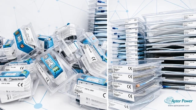
Match the complete marking
Match the complete Bently Nevada 330701-00-25-90-02-00 marking and the actual installed hardware configuration before approving the order. Verify the fully threaded imperial case, nine-metre lead and unarmored ClickLoc connection.
-
Check the offered item before ordering
Request clear photographs of the offered 330701-00-25-90-02-00 and ask your maintenance team to compare its markings and interfaces with the installed equipment and applicable Bently Nevada instructions.
Technical specifications for 330701-00-25-90-02-00
-
Manufacturer:Bently Nevada
-
Product Category:Machinery Monitoring Systems
-
Spare Part Number:330701-00-25-90-02-00
-
Weight:0.1 kg
-
Tariff Code:8537101190
-
Tip diameter:11 mm
-
Case thread:1/2-20 UNF
-
Unthreaded case length:0.0 in
-
Overall case length:2.5 in
-
Total probe length:9.0 m
-
Cable construction:Standard, unarmored
-
Connector:Miniature coaxial ClickLoc
-
Probe resistance:8.5 +/-1.1 ohm
-
Matched-system scale:3.94 V/mm nominal
-
Matched-system linear range:4.0 mm
Information
- Bently Nevada 330701-00-25-90-02-00 places the sensing tip at the shaft while its long integral lead reaches a matching conditioner without an additional extension-cable junction.
Installation focus: Thread engagement and stable target clearance
Calibration boundary: Complete matched 11 mm transducer system
The fully threaded imperial case gives adjustment at the mounting point. The selected case length does not establish the operating gap: bracket position, target movement and usable linear range must be checked separately. The ClickLoc connection provides a locking coaxial interface.
System performance depends on the companion 11 mm Proximitor and target conditions. The standard calibration uses AISI 4140 steel; another material or a small target can change the voltage-versus-gap relationship and requires an application-specific evaluation.
330701-00-25-90-02-00 Original Technical Excerpt
Bently Nevada 3300 XL 11 mm Proximity Transducer System, 146256 Rev. T. Selected original pages retain the applicable technical tables and interface context. PDF · 6 pages.330701-00-25-90-02-00 Installation & Verification Guide
Apter Power field guide covering nine-metre route, imperial engagement, long-lead handling, validation and handover. PDF · 5 pages.
Application scope: Select compatible companion hardware and retain the intended measurement or control function. Accessories are included only when itemized in the offered assembly.
Remote conditioner positioning
The nine-metre integral lead can reach the matching conditioner without an added extension.Imperial probe brackets
Use the fully threaded half-inch case in a matching rigid mounting arrangement.Shaft vibration monitoring
Connect the calibrated 11 mm chain to a monitor with its correct scale.Axial displacement measurement
Assess shaft travel against the usable gap range on the actual target.
Identify the conditioner calibration and the full integral lead route before loosening the probe. Retain the existing target material and working-gap record.
Check the 1/2-20 mounting provision and the permitted thread engagement. Position the sensing end clear of surrounding metal and secure the bracket without loading the cable.
Route the factory cable with protected bends and strain relief. Inspect the ClickLoc mating faces and preserve the complete lead without repairs that alter its electrical length.
With the machine in the approved test state, use controlled target movement to compare local gap voltage, polarity and incremental response with the intended transducer configuration.
Compare the remote display with the conditioner result and the configured engineering scale. Exercise the required alarms and restore only the maintenance controls that the test has cleared.
Retain the final 330701-00-25-90-02-00 identity, wiring and verified configuration with the machine maintenance record.
Alternative Names
Technical notes
Electrical length: Connect the nine-metre probe to the matching nine-metre 11 mm conditioner. Additional cable changes the calibrated chain; preserve the factory lead and assess routing before installing the probe.
Mounting engagement: For the 1/2-20 case, the maximum thread engagement is 0.750 in. A long threaded case does not authorize burying the tip region in surrounding metal; keep the sensing area clear.
System validation: At the standard target and calibration conditions, the system uses a recommended 2.5 mm gap. Validate gap voltage and incremental response together before relying on the monitor scale.

FAQ View All FAQ
-
Why should 330701-00-25-90-02-00 normally reach the conditioner without an extension cable?Its integral probe lead already supplies the nine-metre electrical length. Adding an extension changes the tuned transducer chain, so the conditioner and complete cable arrangement must be matched.
-
Can excess lead on 330701-00-25-90-02-00 be cut to fit the cabinet route?No. Cutting or splicing changes electrical characteristics and connector integrity. Plan a protected route for the factory lead while respecting bend and strain limits.
-
Does the long threaded case of 330701-00-25-90-02-00 permit unlimited engagement into a bracket?No. The 1/2-20 case has a maximum engagement limit of 0.750 in. Excess surrounding metal near the sensing end can influence the measurement.
-
How does a different shaft material affect 330701-00-25-90-02-00?The standard system calibration uses AISI 4140 steel. A different conductive material can change sensitivity and linearity, so verify the actual target rather than applying the standard scale without evaluation.
-
Why can a correct static gap voltage on 330701-00-25-90-02-00 still leave a measurement problem?One voltage point does not verify the slope or complete travel range. Check controlled displacement, polarity and available linear travel around the working position.
-
What changes are needed when 330701-00-25-90-02-00 replaces a 7200-series probe?The 3300 XL 11 mm conversion requires compatible probes, cables and conditioners as a complete system, together with suitable monitor configuration. It is not a probe-only substitution.
-
How should adjacent probes be considered when locating 330701-00-25-90-02-00?Target size, shaft diameter and tip separation affect electromagnetic cross-talk. Evaluate the complete geometry when space is restricted instead of assuming that each probe is independent.
-
Why should 330701-00-25-90-02-00 be checked at the monitor as well as at the conditioner?The field wiring and monitor configuration complete the signal path. Correct local gap response does not prove the remote scaling, polarity, filtering or alarm action.
Supporting new and legacy automation
-
Please try to be as accurate as possible with your search.
-
We can quote you on 1000s of specialist parts, even if they are not listed on our website.
-
We can't find any results for “”.
Related cases and sourcing guidance
View all case studiesYou May Also Like
Product Browsing History
-
Whatsapp: +86 18030235313
Send us a message. -
sales13@apterpower.com
Complete our online form. -
+86 18030235313
Speak to our team in your native language.