-
Match the complete marking
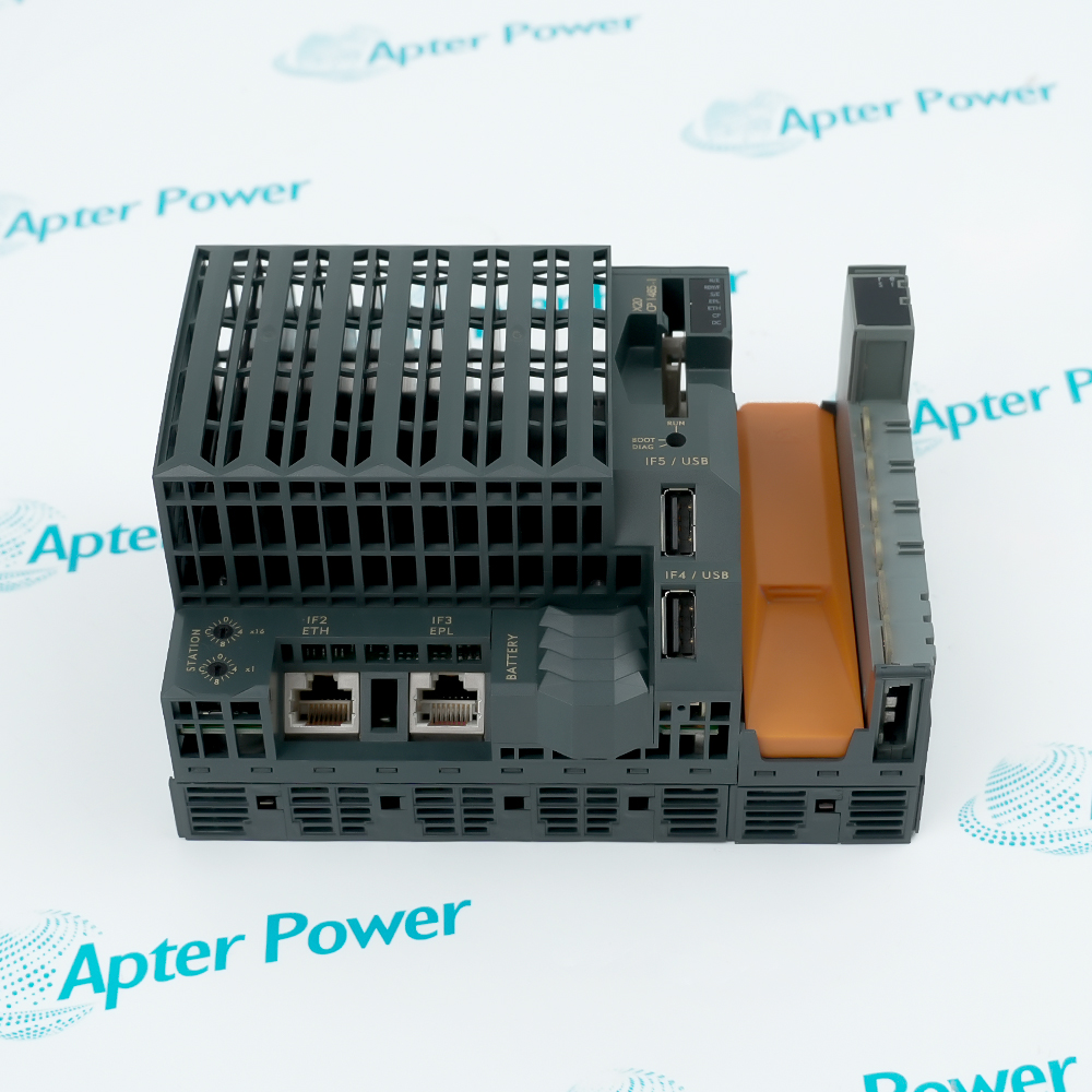
Match the complete B&R X20AI4632 marking, hardware revision and selected configuration to the installed position. Check analog channels and voltage range against the installed configuration.
-
Check the offered item before ordering
Request label and connection photographs. Have your maintenance team compare the offered X20AI4632 with the installed equipment and applicable B&R instructions.
Technical specifications for X20AI4632
-
Manufacturer:B&R
-
Product Category:PLC Systems
-
Spare Part Number:X20AI4632
-
Weight:0.02 kg
-
Tariff Code:8537101190
-
Analog channels:4 differential inputs
-
Voltage range:+/-10 V
-
Current range:0 to 20 mA
-
Conversion time:50 microseconds for all inputs
-
Converter:SAR, 16-bit
-
Voltage input impedance:20 megohms
-
Current input load:Less than 400 ohms
-
Common-mode range:+/-12 V
-
Hardware filter:Third-order low-pass, 10 kHz cutoff
-
Isolation test:500 Veff channel to bus
-
Internal I/O consumption:1.5 W
-
Bus consumption:0.01 W
Information
- B&R X20AI4632 captures four signals in the same 50 microsecond conversion interval, helping keep related process measurements aligned in time.
Voltage range: +/-10 V
Current range: 0 to 20 mA
The SAR conversion produces signed voltage data and nonnegative current data. Per-channel filtering and user scaling adapt the acquired values to the application, while configurable limit analysis and trace functions support signal examination.
Inputs are isolated from the bus but not from one another. Observe the +/-12 V common-mode range and separate this module from the listed controller, bus-receiver and supply modules by at least one module to reduce disturbance.
X20AI4632 Official Technical Excerpt
Original B&R technical material applicable to X20AI4632, covering function, interfaces and operating limits. PDF · 8 pages.X20AI4632 Installation & Verification Guide
Apter Power field guide for the selected connection, configuration and functional tests. PDF · 5 pages.
Application scope: The technical values apply to this model in the specified installation and configuration. The examples below address the stated product function.
Synchronized analog capture
Observe four related voltage or current measurements within a common conversion interval.Mixed signal wiring
Connect voltage and current transmitters to their respective channel terminals.Transient analysis
Use sampled-value recording and trace settings to examine fast analog events.Software threshold monitoring
Apply individual scaling, filtering and limit analysis to the acquired signals.
Identify each transmitter and its positive voltage or current terminal.
Measure relevant field potentials before reconnecting.
Compare the station order with the connection guidance.
Check which channels are unused and apply the recommended bridge or current configuration to reduce dissipation.
Restore the filter assigned to each channel rather than copying one setting across all four.
Apply a known input within the selected range and compare raw INT data with the scaled engineering value.
Alternative Names
Technical notes
Preserve shared reference conditions: Measure relevant field potentials before reconnecting. The module has bus isolation but no channel-to-channel isolation, and the common-mode range is +/-12 V; separate isolated transmitters do not make the input channels independently isolated.
Reapply individual input filters: Restore the filter assigned to each channel rather than copying one setting across all four. Fast transients and slowly varying process signals can need different filtering even when their electrical ranges are the same.
Review limit and overload behavior: Exercise the configured threshold with a controlled signal and verify the intended application response. Distinguish user-defined limit events from converter range overshoot and synchronization errors before returning the inputs to control.

FAQ View All FAQ
-
Are the four X20AI4632 channels converted one after another?All four inputs are converted within a 50 microsecond conversion interval, supporting simultaneous signal acquisition.
-
How is current input selected on X20AI4632?Wire the signal to the current-input terminal rather than the voltage-input terminal and use the corresponding channel settings. The two signal types use different positive terminals.
-
What loading does X20AI4632 present to a voltage transmitter?Voltage input impedance is 20 megohms within the signal range. Confirm the source and common-mode conditions as well as the nominal signal amplitude.
-
Can X20AI4632 isolate one field transmitter from another?No. The channels are isolated from the bus but not from each other, so inter-channel potential differences must stay within the permitted common-mode range.
-
Why should unused X20AI4632 inputs be bridged or configured for current?This reduces internal power dissipation. Apply the method appropriate to the unused terminal arrangement and keep inactive channels out of process calculations.
-
Does an open input always produce an open-line indication on X20AI4632?Open-line detection is available for voltage measurement only. A zero current reading cannot automatically be interpreted as a detected cable break.
-
What can the trace function on X20AI4632 record?It records sampled analog values for signal analysis. Select the sampling, trigger and record settings appropriate to the event being investigated.
-
Why is module spacing relevant when installing X20AI4632?At least one module must separate it from the specified controller, X20BR9300 and listed X20 supply modules to prevent disturbances in the analog measurement.
Supporting new and legacy automation
-
Please try to be as accurate as possible with your search.
-
We can quote you on 1000s of specialist parts, even if they are not listed on our website.
-
We can't find any results for “”.
Related cases and sourcing guidance
View all case studiesYou May Also Like
Product Browsing History
-
Whatsapp: +86 18030235313
Send us a message. -
sales13@apterpower.com
Complete our online form. -
+86 18030235313
Speak to our team in your native language.