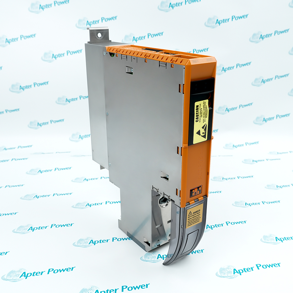
-
Match the complete marking
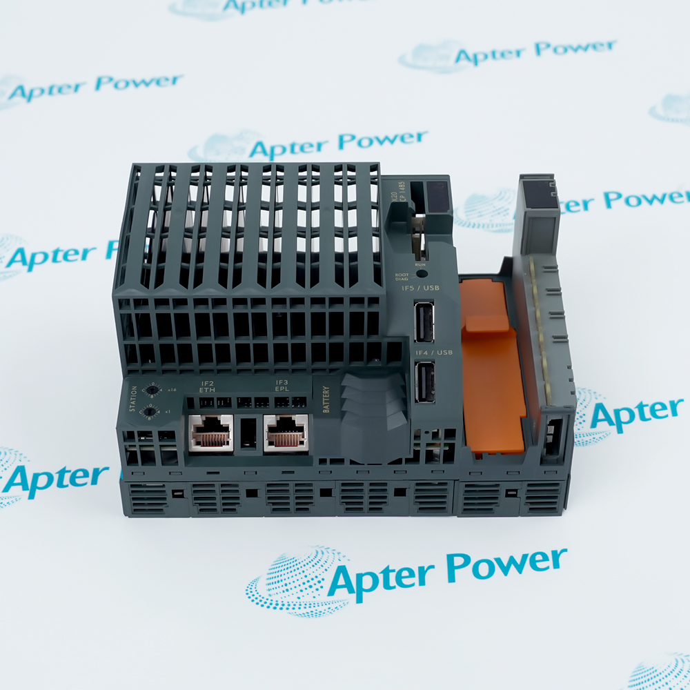
Provide the complete B&R X20AI2222 marking. Match X20AI2222 and the installed terminal and filtering arrangement.
-
Check the offered item before ordering
Request available label and connector photos. Have your maintenance team compare the offered X20AI2222 with the installed equipment and applicable B&R instructions.
Technical specifications for X20AI2222
-
Manufacturer:B&R
-
Product Category:PLC Systems
-
Spare Part Number:X20AI2222
-
Weight:0.02 kg
-
Tariff Code:8537101190
-
Inputs:2 differential voltage channels
-
Input range:±10 V
-
ADC resolution:13 bits including sign
-
Conversion time:300 µs for both inputs
-
Value format:Signed INT
-
Converter increment:2.441 mV; data-word step 8
-
Input impedance:20 MΩ
-
Digital-filter sample interval:1 ms when enabled
-
Interchannel sample offset:200 µs when filtering
-
Internal I/O consumption:0.8 W
-
Bus consumption:0.01 W
-
Terminal options:X20TB06 or X20TB12
Information
- B&R X20AI2222 supports a small pair of voltage measurements where adjustable signal conditioning is more useful than adding unused analog channels.
Data: Signed INT with 2.441 mV increments
Timing: 300 µs conversion before filter/network effects
The module is designed for a six-pin X20 terminal block, with a twelve-pin block also permitted when needed. It consumes 0.8 W from the internal I/O supply and 0.01 W from the bus; unused inputs should be bridged at the terminal as recommended for lower dissipation.
When the digital filter is enabled, input sampling occurs at millisecond intervals with a 200 µs offset between channels and asynchronously to the network cycle. Filtering and ramp limiting therefore affect the temporal relationship between a physical input step and its reported value.
X20AI2222 Official Technical Excerpt
B&R X20AI2222: original manufacturer technical information covering the specified interfaces and operating limits. PDF · 10 pages.X20AI2222 Installation & Verification Guide
Apter Power installation and verification guide covering choose the two-channel mapping, verify signal and reference wiring, set the signed conversion scale, apply a known input step, test polarity and channel identity. PDF · 5 pages.
Application scope: The applications below describe its technical role. Select associated hardware and configuration for the actual installation.
Two-signal voltage measurement
Acquire a pair of bipolar process signals without a larger analog module.Compact terminal installations
Use the designed six-pin terminal arrangement or the permitted twelve-pin alternative.Filtered process tracking
Apply digital filtering where the additional response delay suits the measured variable.Raw-value verification
Compare signed process words with calibrated voltage inputs using the actual converter increment.
Use the intended X20TB06 or permitted X20TB12 arrangement. Compare the actual input pin allocation rather than assuming all terminal positions are active.
Bridge any unused input at the terminal according to the applicable wiring guidance. Do not leave its diagnostic state unexplained in the application.
Allow for millisecond sampling and the 200 µs interchannel offset when comparing changing signals. Avoid assuming simultaneous samples from two matching displayed values.
Confirm that the cycle time exceeds 500 µs if the digital filter is required. Resolve a disabled filter through configuration rather than replacing a functioning module.
Save terminal type, used and bridged channels, signed scaling, filter settings and response measurements. These details preserve the intended behavior after future replacement.
Apply positive, zero and negative values to one channel at a time. Confirm that only the intended signed application variable responds.
Alternative Names
Technical notes
Operating boundary: A data-word step of eight represents one converter increment. Raw-word arithmetic must account for that representation when comparing resolution with voltage.
Integration details: Preserve terminal choice, channel reference wiring, signed scaling and filtered-sampling assumptions when replacing X20AI2222.
Technical basis: B&R X20AI2222 Data Sheet, V1.30. X20AI2222 is the two-input ±10 V module. The 300 µs conversion time does not include every filter and network-cycle contribution.

FAQ View All FAQ
-
What is the smallest converter increment of X20AI2222?One ADC increment is 2.441 mV and appears as an increment of eight in the signed process-data word.
-
Which terminal blocks can be used with X20AI2222?The module is designed for X20TB06, while X20TB12 can also be used when required by the installation arrangement.
-
Are filtered measurements from the two channels of X20AI2222 simultaneous?No. With filtering enabled, the channel sampling has a 200 µs offset and occurs asynchronously to the network cycle.
-
What sampling interval is used by the enabled digital filter of X20AI2222?The channels are sampled at millisecond intervals. This is separate from the 300 µs conversion time for both inputs.
-
Why does X20AI2222 use a signed INT process value?The ±10 V measurement range includes both polarities. The signed representation preserves negative as well as positive input values.
-
How should an unused input on X20AI2222 be handled?B&R recommends bridging unused inputs at the terminal to reduce power dissipation, following the appropriate terminal wiring arrangement.
-
Can ramp limiting on X20AI2222 operate while its filter is disabled?No. Ramp limiting is performed in conjunction with filtering and acts on the input before the filter stage.
-
What happens if the cycle time for X20AI2222 is shorter than the filter's minimum?The configurable filter is disabled for cycle times that do not exceed 500 µs. Check the actual cycle before expecting filtered behavior.
Supporting new and legacy automation
-
Please try to be as accurate as possible with your search.
-
We can quote you on 1000s of specialist parts, even if they are not listed on our website.
-
We can't find any results for “”.
Related cases and sourcing guidance
View all case studiesYou May Also Like
Product Browsing History
-
Whatsapp: +86 18030235313
Send us a message. -
sales13@apterpower.com
Complete our online form. -
+86 18030235313
Speak to our team in your native language.