Speak to a sourcing specialist
sales13@apterpower.com

X20AI4222

Analog Input Module
Ships by Thursday, November 12
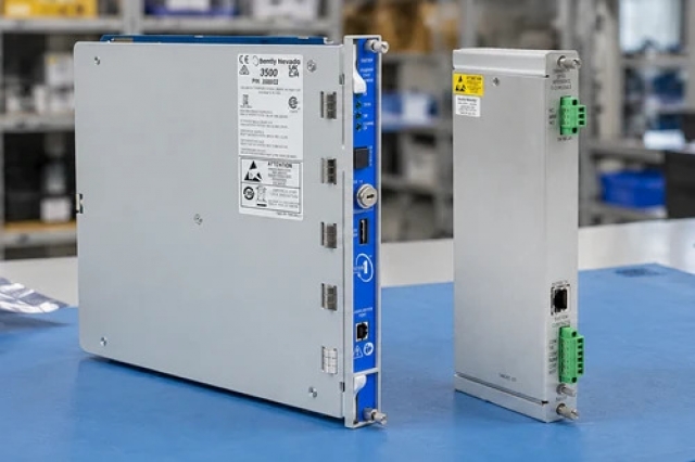
Product image is representative; revision or series may vary. Contact us to request a specific version.

Product Describe:

B&R X20AI4222 acquires four differential ±10 V signals with a 13-bit converter, configurable filtering and channel diagnostics in an X20 I/O station.
  • Manufacturer part number
    X20AI4222
  • Shipping
    Swift global dispatch
  • Condition
    New, original product
  • Shipping size (est.)
    10cm x 6cm x 1.5cm
  • Country of Origin
    Austria
Get a quick price for X20AI4222
E-mail *
Mobile *
Company
Content *
Quantity *
Upload (gif, jpg, jpeg, png, bmp, doc, docx, xls, xlsx, ppt, pdf, csv)
For more information on how your data is processed and stored by Apterpower please read our privacy policy

What happens after you enquire

  • 0

    Review your reference

    Send the complete B&R X20AI4222 reference, label photographs and required quantity. Verify X20AI4222 and all four channel assignments.

  • 1

    Confirm the offer

    Review the offered revision, condition, included items and documents against the confirmed installation.

  • 2

    Arrange dispatch

    Confirm quantity, dispatch date, lead-time start and delivery details in the quotation.

  • Match the complete marking

    Provide the complete B&R X20AI4222 marking. Verify X20AI4222 and all four channel assignments.

  • Check the offered item before ordering

    Request available label and connector photos. Have your maintenance team compare the offered X20AI4222 with the installed equipment and applicable B&R instructions.

Technical specifications for X20AI4222

  • Manufacturer:
    B&R
  • Product Category:
    PLC Systems
  • Spare Part Number:
    X20AI4222
  • Weight:
    0.04 kg
  • Tariff Code:
    8537101190
  • Inputs:
    4 differential voltage channels
  • Measurement range:
    ±10 V
  • Converter resolution:
    13 bits including sign
  • Conversion time:
    400 µs for all inputs
  • Input impedance:
    20 MΩ
  • Maximum input signal:
    ±30 V
  • Analog filter:
    Third-order low-pass, 1 kHz cutoff
  • Common-mode range:
    ±12 V
  • Channel-to-bus test voltage:
    500 V RMS
  • Channel-to-channel isolation:
    None
  • Internal I/O consumption:
    1.1 W
  • Bus consumption:
    0.01 W

Information

Overview Downloads Applications / Compatibility Product Precautions
  • B&R X20AI4222 brings four bipolar voltage measurements into the controller while allowing the input processing to suppress unwanted spikes and report out-of-range conditions.
Acquisition: Four ±10 V differential inputs
Conversion: 400 µs for all channels
Processing: Configurable filter and ramp limiting
The four differential inputs use a 13-bit converter including sign, with 400 µs conversion time for all inputs. Input impedance is 20 megohms within the signal range, and the maximum permissible input signal is ±30 V rather than an extended measurement range.

The analog front end includes a third-order low-pass filter with a 1 kHz cutoff. Configurable digital filtering and input ramp limiting act separately; ramp limiting precedes the digital filter and requires filtering to be enabled.

Channels are isolated from the bus but not from one another. Individual input LEDs distinguish valid conversion, open line and range violation. Horizontal operation allows −25 to +60 °C, while vertical mounting reduces the upper limit to +50 °C.
Controller platform reference: X20 differential voltage acquisition. Match the installed configuration and applicable instructions.
B&R X20AI4222: original manufacturer technical information covering the specified interfaces and operating limits. Installation topics include: assign all four voltage channels, fit the correct x20 connection set, select the digital filter, test positive and negative values, confirm orientation and temperature.
Original manufacturer pages retain their technical context. Use the Apter Power guide with the applicable manufacturer instructions and approved installation design.
System and supply context: B&R X20AI4222 operates within the following defined system context. Verify X20AI4222 and all four channel assignments.

Application scope: The applications below describe its technical role. Select associated hardware and configuration for the actual installation.
Prepare B&R X20AI4222 for its configured installation using these checks.
Check the common-mode condition

Assess the source reference against the ±12 V common-mode range. Differential measurement does not permit an unrestricted voltage offset to the module reference.

Inspect the source loading

Check the source with the 20-megohm input impedance and the installed cable. Resolve wiring defects before changing filtering to conceal an unstable signal.

Tune ramp limiting deliberately

Use ramp limiting only with the digital filter and select the limit for the real process. Excessive limiting can suppress a valid rapid input change as well as noise.

Check each input indication

Compare the input LEDs and software diagnostics with connected, open and out-of-range test conditions. Perform fault tests only in the approved process state.

Save the four-channel behavior

Retain the channel map, polarity, filter and ramp settings, diagnostics and measured response. Verify that the application receives the intended filtered signal before release.

Confirm orientation and temperature

Check whether the module is horizontal or vertical and apply the corresponding ambient limit. Keep the station enclosure and ventilation within the intended conditions.

Alternative Names

B&R X20AI4222

Technical notes

Operating boundary: The 1 kHz analog low-pass cutoff and the selectable digital filter describe separate processing stages; neither should be treated as the application update rate.

Integration details: Retain the differential wiring, source common mode, bus module, terminal block and filter settings when replacing the four-input module.

Technical basis: B&R X20AI4222 Data Sheet, V1.30. X20AI4222 is the four-input ±10 V module. Conversion time, digital filtering and bus-cycle timing are distinct conditions.


FAQ View All FAQ

  • Are the four inputs of X20AI4222 individually isolated?
    No. The channels are isolated from the bus but not from each other; differential inputs do not imply independent galvanic isolation.
  • Does the ±30 V limit of X20AI4222 extend its calibrated measurement range?
    No. The measurement range is ±10 V. The maximum permissible signal must not be confused with the usable measuring range.
  • What does the 400 µs conversion figure for X20AI4222 include?
    It covers conversion of all four inputs. Digital filtering and communication timing can add further delay to the application value.
  • In what order does X20AI4222 apply ramp limiting and digital filtering?
    Input ramp limiting acts first, followed by filtering. Ramp limiting is only available in conjunction with the filter.
  • How does an input LED on X20AI4222 distinguish an open line from a range error?
    An off input LED indicates an open line or disconnected sensor, while blinking indicates overflow or underflow. A steady indication represents normal conversion with a valid value.
  • What input impedance does X20AI4222 present in its measurement range?
    The specified impedance is 20 megohms, which must be considered with the source and wiring arrangement.
  • Why can a vertically mounted X20AI4222 need a lower ambient limit?
    Vertical operation is rated to +50 °C, compared with +60 °C horizontally. Mounting orientation affects the thermal boundary.
  • Can the digital input filter of X20AI4222 be used at every cycle time?
    No. Its minimum cycle time must be greater than 500 µs; the filter is disabled at shorter cycle times.