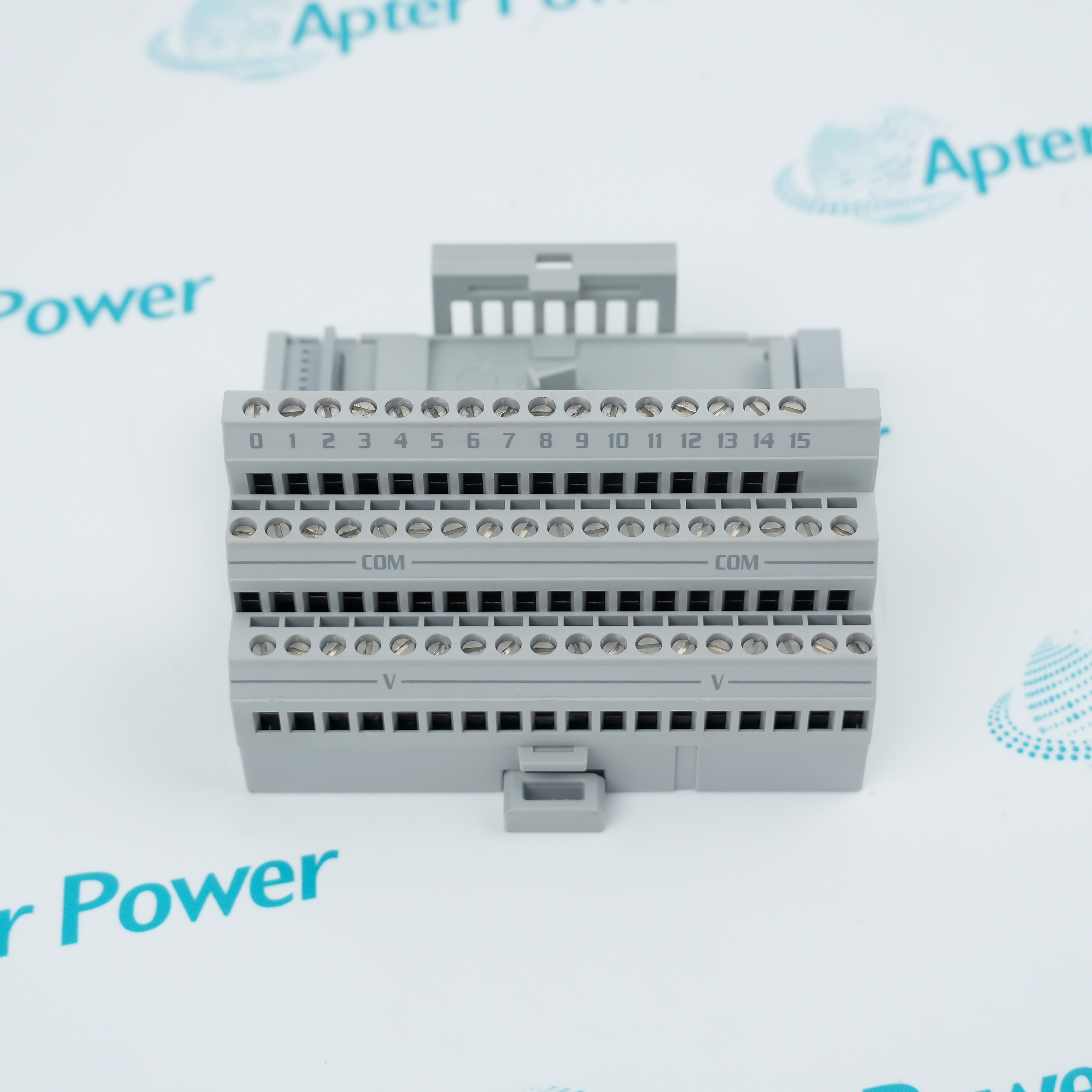
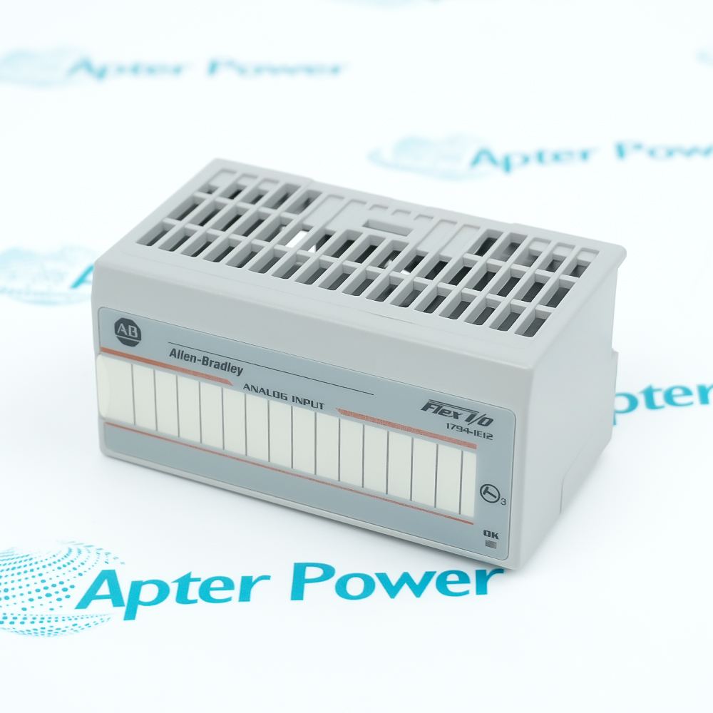
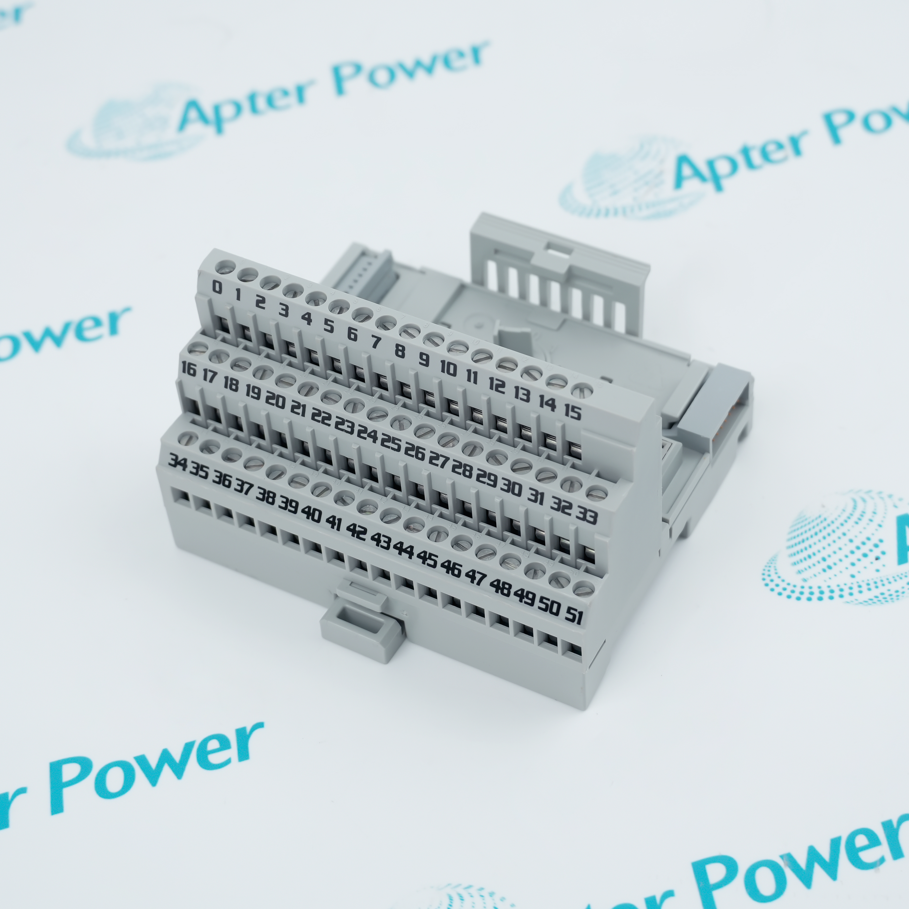
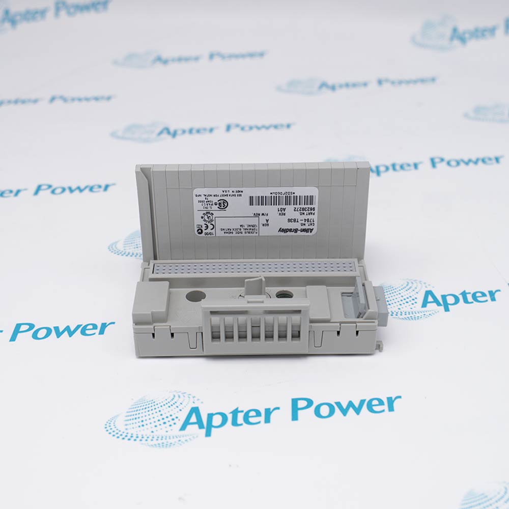
1794-OE4XT is installed with FLEX I/O adapter and backplane, 1794-TB2, TB3, TB3S, TB3T, TB3TS or TBN base, 24 V DC external field supply, compatible analog actuators or reference inputs.
Engineered applications include Valve-positioner command outputs, Variable-speed drive reference signals, Process setpoint generation, FLEX I/O analog-output modernization.
Important Notice: Isolate the FLEX I/O station and field supply, key the terminal base to position 4, preserve channel polarity and commons, then validate each output at low, midpoint and high command values.
The first document presents model-specific technical identity and engineering data. The second provides a separate installation, connection and commissioning workflow.
1794-OE4XT supports this documented Allen-Bradley FLEX I/O analog system engineering task.
Verify the complete 1794-OE4XT marking and its documented Allen-Bradley FLEX I/O analog system position before field work.
Place the connected equipment in the approved maintenance state before removing 1794-OE4XT.
Isolate every applicable power, signal and stored-energy source, then prove a safe state at 1794-OE4XT.
Record the installed connectors, terminals, jumpers and channel or node assignments before disconnection.
Use ESD controls and protect keyed interfaces, edge connectors and exposed electronic assemblies.
Restore only the approved Allen-Bradley FLEX I/O analog system hardware arrangement and configuration after replacement.
Energize 1794-OE4XT in the documented sequence and review local, host and network diagnostics.
Prove the intended controlled function and retain the final acceptance record before production release.