
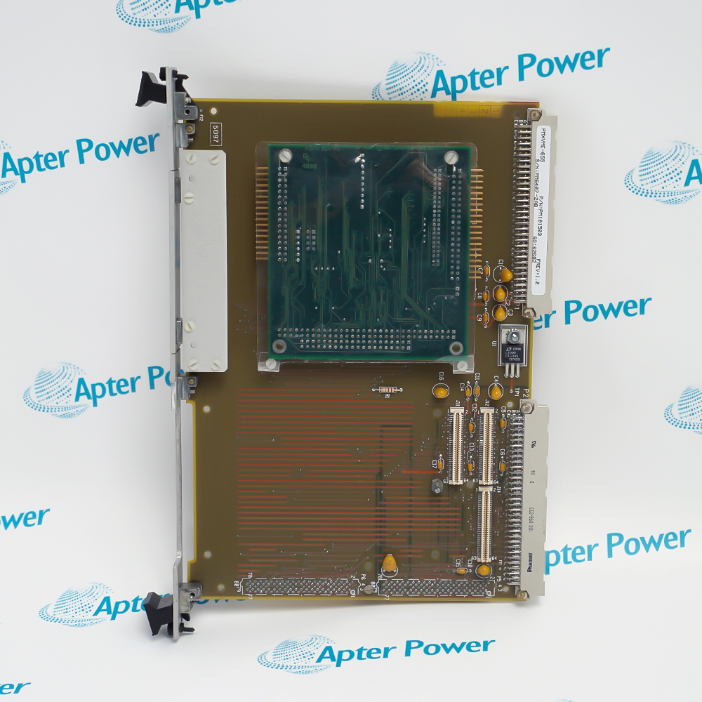

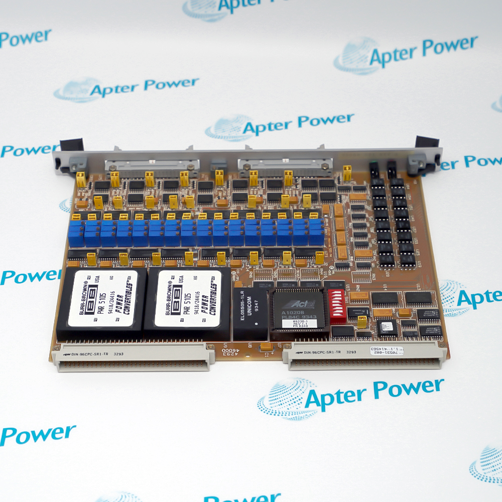
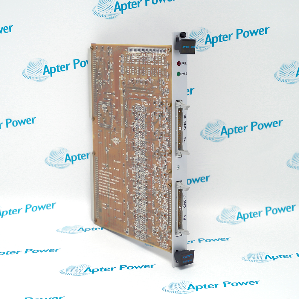
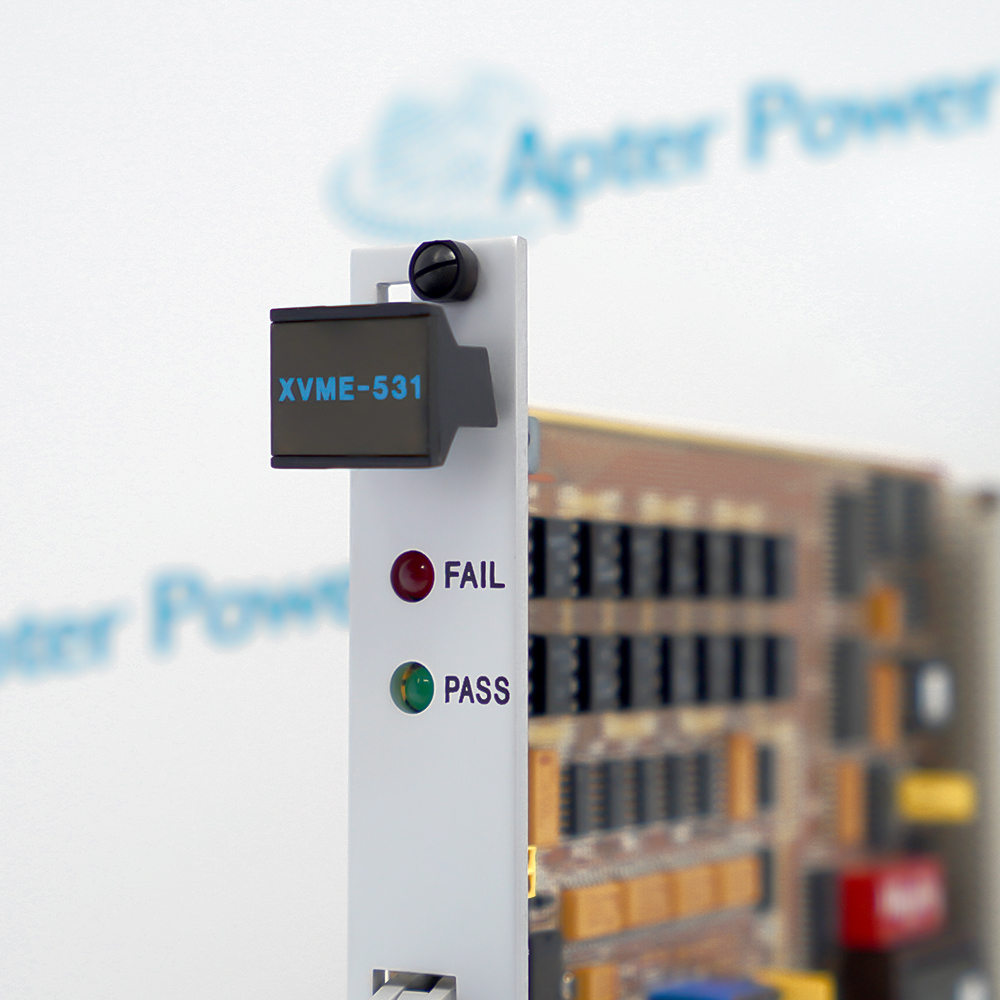











Install XYCOM XVME-531 in a compatible VMEbus chassis and match the programmed output range, load and update mode to the documented control design. Preserve the channel calibration and reset-state jumper selection during replacement.
The commissioning workflow covers VMEbus addressing, output-range confirmation, reset-state checks, channel calibration and controlled output verification.
Important Notice: Confirm the exact XVME-531 identity and I/O map before work. De-energize the VMEbus chassis and field loads, observe ESD-safe handling, and verify every channel with a controlled output test before return to service.
The first document presents exact-model technical data and eight engineering questions. The second preserves the supplied source publication used for model-specific verification.
Drive proportional valves, setpoints and other documented analog loads from sixteen isolated channels.
Provide voltage or 4-20 mA commands to compatible drives using the configured range.
Generate calibrated outputs for panel meters, strip-chart recorders and monitoring instruments.
Coordinate simultaneous updates when several analog commands must change together.
Verify the complete XYCOM XVME-531 marking and installed VMEbus slot before work.
De-energize the VMEbus chassis and all connected analog field circuits before removal or installation.
Use ESD-safe handling and keep the double-high module aligned with the chassis guides and connectors.
Record the configured voltage or current range, gain and offset setting for every active channel.
Confirm that 4-20 mA loads remain within the documented 50-to-525-ohm range and 10.5 V compliance limit.
Preserve the jumper-selected 0000H or 0800H reset state so field devices assume the intended safe output.
Verify the VMEbus address, A24/A16 access and D16/D08(EO) data configuration before energization.
After installation, test all used channels, simultaneous-update behavior and SYSFAIL response before service release.



Copyright Notice © 2026 apterpower.com All rights reserved,Apter Power is not an authorised distributor or representative of the manufacturers featured on this website. Brand names and trademarks featured are the property of their respective owners.