-
Match the complete marking
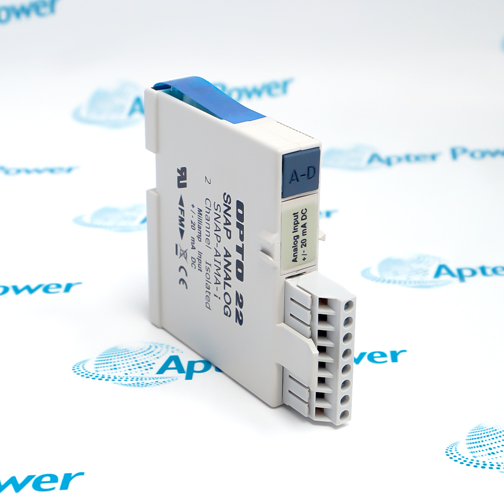
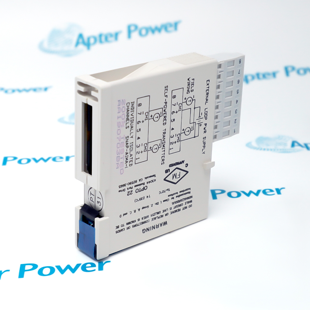
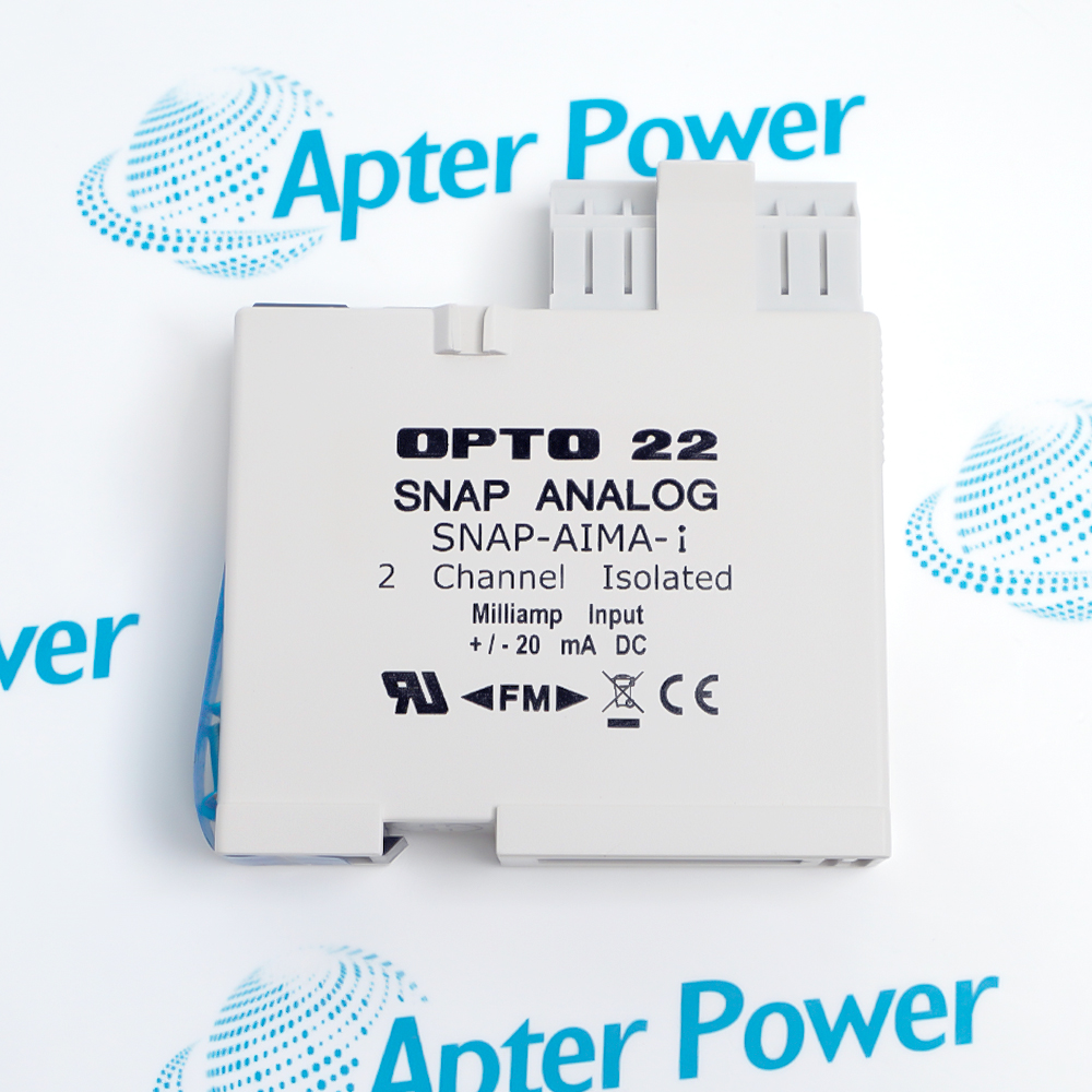
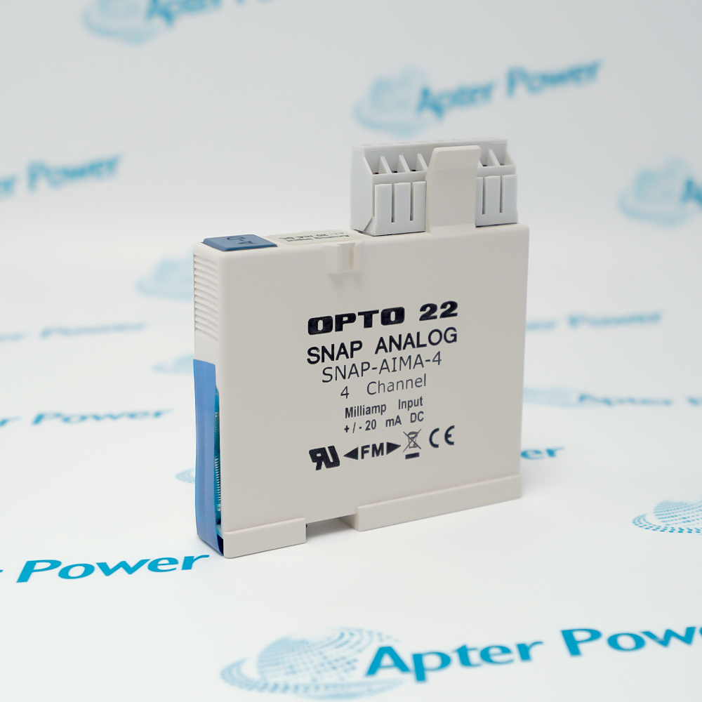
Record the full SNAP-AIMA-I marking, including the final -I suffix, and any visible module revision. Use that exact reference in the enquiry and quotation.
-
Check the offered item before ordering
Request available module label and rack-connector photos. Have your maintenance team compare the offered SNAP-AIMA-I with the installed I/O rack and applicable Opto 22 documentation.
Technical specifications for SNAP-AIMA-I
-
Manufacturer:Opto 22
-
Product Category:PLC Systems
-
Spare Part Number:SNAP-AIMA-I
-
Weight:0.1 kg
-
Tariff Code:8537101190
-
Input channels:2, isolated from one another
-
Input range:−20 to +20 mA
-
Maximum overrange:±10%
-
Resolution:0.8 µA
-
Accuracy:0.05% (10 µA)
-
Data freshness:11 ms
-
Input response:99.9% / 19.9 µA / 10 ms
-
Channel isolation:250 V continuous; 1500 V transient
-
Optical isolation:4000 V
-
Transformer isolation:1500 V
-
Input resistance:200 Ω per channel
-
Maximum survivable input:36 mA or 9 VDC
-
Rack power:5 VDC (±0.15 V) at 200 mA
-
Operating temperature:−20 to +70 °C
-
Field wire size:22 to 14 AWG
Information
- Each channel is isolated from the other channel and from the rack processor. The module measures field current without sourcing transmitter loop power, so external excitation must be provided where the instrument requires it.
Wiring review: Trace each field pair and its supply before reconnection
Controller mapping: Preserve the two point assignments in the PAC strategy
Acceptance focus: Challenge both inputs with a controlled current source
The datasheet describes optical isolation at 4000 V, transformer isolation at 1500 V and channel-to-channel isolation of 250 V continuous, with a 1500 V transient rating. The module mounts on a SNAP PAC rack; verify rack capacity, I/O processor compatibility and field circuit design before replacement.
The module uses a 5 VDC rack supply at 200 mA, has 200 Ω input resistance per channel and survives an input of 36 mA or 9 VDC. Its factory calibration removes field adjustment, but the controller strategy must still scale the raw current correctly for each instrument.
-
Apter Power technical reference for Opto 22 SNAP-AIMA-I
Prepared by Apter Power - PDF, 5 pages. Model-specific electrical data, field-loop integration and service checks. -
Opto 22 SNAP-AIMA-I installation guide
Prepared by Apter Power - PDF, 2 pages. Field-loop review, installation checks and commissioning evidence.
Application scope: Use for isolated bipolar current acquisition where the configured controller strategy applies the correct engineering scale.
-
Separate field references
Acquire two grounded instruments without tying their signal references together at the module input. -
Bipolar signal capture
Use the documented −20 to +20 mA measurement span where an application requires signed current values. -
SNAP PAC integration
Place the module on a compatible rack and map both channels through the installed I/O processor and control strategy. -
Maintenance replacement
Retain each channel’s source, polarity and scaling while exchanging an exact-model input module.
Remove rack and loop power under the site isolation procedure before wiring the pluggable connector.
SNAP-AIMA-I does not source excitation; verify the external loop supply and return path before diagnosing a zero reading.
Keep normal current within the selected range and avoid exceeding the stated 36 mA or 9 VDC survivability limit.
Do not bridge the two channel returns or defeat the designed field grounding solely to simplify wiring.
Align the 20-pin module connector with the keyed 24-pin rack position and use the specified retention hardware.
Apply known signed-current test points and compare processor readings with the original engineering scale.
Alternative Names
Technical notes
Installation relationship: Two isolated field-current channels connect through a SNAP PAC rack to a compatible I/O processor and application strategy.
Loop-power boundary: This model measures current without transmitter excitation; external supply and field return remain part of the installed loop.
Technical reference: Opto 22 SNAP Isolated Analog Input Modules, Form 1182-240326, pp. 1 and 4; exact SNAP-AIMA-i specification table.

FAQ View All FAQ
-
Why might SNAP-AIMA-I show zero for a healthy two-wire transmitter?The module does not furnish loop excitation. Check the external supply, loop continuity, polarity and transmitter demand, then read the channel value and fault state through the rack processor.
-
How should the two SNAP-AIMA-I channels be grounded?Treat the channels as separately isolated measurement paths. Follow each instrument loop drawing and rack grounding design; do not add a common bridge between channel returns simply because the signals share one module.
-
Can SNAP-AIMA-I be exchanged for the SNAP-AIMA-iSRC sourcing model without a wiring review?No. The iSRC has a separate 24 V loop-source arrangement, whereas SNAP-AIMA-I measures current only. Verify the field supply and connector wiring before selecting a replacement variant.
-
What test points help verify SNAP-AIMA-I scaling?Use a calibrated current source at representative negative, zero and positive values within −20 to +20 mA. Compare raw channel values and engineering units in the controller strategy and record as-left results.
-
What rack conditions should be checked before fitting SNAP-AIMA-I?Confirm the rack and I/O processor are compatible and the 5 V supply budget includes 200 mA for this module. Align the keyed connector and secure the retention hardware without forcing the pins.
-
How can a noisy SNAP-AIMA-I reading be traced?Compare both channels separately, inspect shield routing and field grounding, and inject a stable current at the terminal connector. The isolated inputs reduce ground-loop coupling but do not correct an unstable source or bad wiring.
-
What does the SNAP-AIMA-I 250 V channel-isolation figure represent?It is the documented continuous channel-to-channel isolation rating; the datasheet separately lists a 1500 V transient value. Assess the complete field circuit and safety requirements rather than using the module rating as a substitute for installation design.
-
Is field calibration needed after replacing SNAP-AIMA-I?The module is factory calibrated and has no user adjustment. Still verify both channels using known currents and confirm that the controller scaling, alarm thresholds and recorded values match the installed application.
Supporting new and legacy automation
-
Please try to be as accurate as possible with your search.
-
We can quote you on 1000s of specialist parts, even if they are not listed on our website.
-
We can't find any results for “”.
Related cases and sourcing guidance
View all case studiesYou May Also Like
Product Browsing History
-
Whatsapp: +86 18030235313
Send us a message. -
sales13@apterpower.com
Complete our online form. -
+86 18030235313
Speak to our team in your native language.