-
Match the complete marking
Include MMS6120 and any revision or assembly number visible on the item. Keep the exact reference on your enquiry and quotation.
-
Check the offered item before ordering
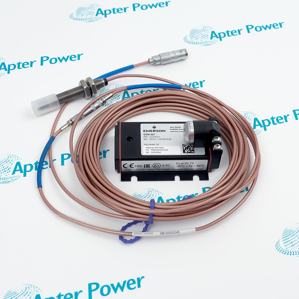
Request current label and front-panel and connector photos. Have your maintenance team compare the offered MMS6120 with the installed equipment and applicable Emerson documentation.
Technical specifications for MMS6120
-
Manufacturer:Epro
-
Product Category:Machinery Monitoring Systems
-
Spare Part Number:MMS6120
-
Weight:0.3 kg
-
Tariff Code:8537101190
-
System family:MMS 6000
-
Input channels:Two electrodynamic velocity-sensor channels
-
Sensor family:PR9266–PR9268 velocity sensors
-
Measurement modes:V RMS, S op and S peak-to-peak
-
Local interface:RS-232
-
Host interface:RS-485
-
Supply:18–31.2 V DC, 24 V nominal
-
Module operating temperature:0–65 °C
Information
- The MMS6120 fits an MMS 6000 monitoring architecture; its bearing-vibration channels depend on the installed velocity sensors, alarm configuration and host integration.
Configuration focus: Per-channel mode and alarms
Replacement check: Preserve sensor axis and host mapping
The MMS 6000 architecture supports local parameterization and connection to a host diagnosis system. Measurement mode, range, filtering, warning and danger limits are part of the installed machine configuration rather than properties of the loose module alone.
For a replacement, retain sensor orientation, cabling, channel identification, range and limit settings. Verify the measurement against a controlled reference and check alarms and host communication before returning a protected machine to normal operation.
-
Epro MMS6120 technical reference
Apter Power technical reference - PDF, 2 pages. Product identity, verified interface data and applicability conditions. -
Epro MMS6120 installation guide
Prepared by Apter Power - PDF, 1 page. Configuration review, safe installation and functional acceptance.
Compatibility scope: Match the installed PR9266–PR9268 sensor execution, channel sensitivity, monitoring range, alarm assignment and MMS 6000 rack interface.
Turbine bearing vibration
Use a correctly oriented velocity sensor to monitor absolute motion at a turbine bearing housing.Compressor casing vibration
Feed casing-motion measurements into an MMS 6000 machine-protection or condition-monitoring channel.Pump vibration trend
Track supported velocity or displacement-derived quantities at a suitable pump measurement location.Fan bearing monitoring
Assess bearing-housing vibration with the compatible PR926x sensor and configured monitor range.
Confirm the electrodynamic transducer axis and mounting point for each channel.
Preserve the selected vibration quantity, range and filter settings.
Document warning and danger values, delays and contact behavior.
Inspect sensor connections, shielding and channel assignments before energization.
Confirm RS-485 addressing and transmitted channel values.
Compare the output to a controlled vibration test or approved running-machine baseline.
Alternative Names
Technical notes
Technical basis: EPRO MMS 6120 Dual Channel Bearing Vibration Monitor, manufacturer-original data sheet.
Applicability: Manufacturer-original MMS6120 data apply to the base monitor. Confirm the offered revision, paired sensors and alarm configuration against the installed system.
Measurement interpretation: Velocity-sensor direction, mounting stiffness and the selected measurement mode affect the bearing-vibration value. Alarm limits belong to the configured machine channel, not to the spare monitor alone.

FAQ View All FAQ
-
How is sensor orientation checked for MMS6120?Compare the transducer sensitive axis with the intended machine vibration direction and the installation drawing.
-
What causes unequal channel readings on MMS6120?Different mounting points, sensor orientation, cabling, configured range or actual machine motion can all contribute; compare them systematically.
-
How should alarm settings be transferred to MMS6120?Record each channel’s warning, danger, delay and contact configuration before service and load the approved values afterward.
-
Can a displacement probe replace a velocity sensor on MMS6120?Not without an approved signal-conditioning arrangement. This module is designed for compatible electrodynamic velocity-transducer inputs.
-
What should be tested after fitting MMS6120?Verify sensor signal, displayed measurement, alarm behavior and host value for each channel under controlled conditions.
-
How is communication loss distinguished from a sensor fault on MMS6120?Check local channel indication and sensor wiring separately from the RS-485 host connection and addressing.
-
Which mechanical locations suit MMS6120?Use rigid bearing-housing or casing points where the selected sensor axis captures the intended absolute motion.
-
What configuration record should accompany MMS6120?Keep the sensor identities, mounting axes, channel ranges, limits, relay logic and host mapping.
Supporting new and legacy automation
-
Please try to be as accurate as possible with your search.
-
We can quote you on 1000s of specialist parts, even if they are not listed on our website.
-
We can't find any results for “”.
Related cases and sourcing guidance
View all case studiesYou May Also Like
Product Browsing History
-
Whatsapp: +86 18030235313
Send us a message. -
sales13@apterpower.com
Complete our online form. -
+86 18030235313
Speak to our team in your native language.