-
Match the complete marking
Include MMS6410 and any revision or assembly number visible on the item. Keep the exact reference on your enquiry and quotation.
-
Check the offered item before ordering
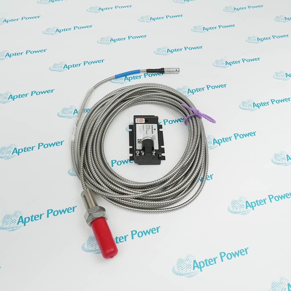
Request current label and front-panel and connector photos. Have your maintenance team compare the offered MMS6410 with the installed equipment and applicable Emerson documentation.
Technical specifications for MMS6410
-
Manufacturer:Epro
-
Product Category:Machinery Monitoring Systems
-
Spare Part Number:MMS6410
-
Weight:0.3 kg
-
Tariff Code:8537101190
-
System family:MMS 6000
-
Input channels:Two independent inductive-sensor channels
-
Transducer configurations:Half bridge, full bridge or differential transformer
-
Signal frequency:Up to 100 Hz
-
Channel processing:Individual, sum or difference
-
Local interface:RS-232
-
System interface:RS-485
-
Example paired sensor:PR9350 inductive displacement family
Information
- The MMS6410 fits an MMS 6000 monitoring architecture; its displacement channels depend on the installed transducers, bridge setup and host integration.
Configuration focus: Bridge mode and channel mathematics
Replacement check: Preserve zero and scaling
The amplifier supports static displacement and dynamic signals up to the documented signal-frequency limit. The balance of sensor supply to ground helps suppress industrial disturbances. Zero adjustment and zero shift can be set independently of the selected measurement range.
RS-232 provides local configuration and reading access; RS-485 connects the monitor to an MMS analysis system or host computer. Preserve sensor wiring, bridge configuration, scaling and channel-combination logic before replacement and verify the readings against a known mechanical reference.
-
Epro MMS6410 technical reference
Apter Power technical reference - PDF, 2 pages. Product identity, verified interface data and applicability conditions. -
Epro MMS6410 installation guide
Prepared by Apter Power - PDF, 1 page. Configuration review, safe installation and functional acceptance.
Compatibility scope: Select compatible PR9350 transducers and the intended bridge/excitation connection for each input; check the host rack and output assignment.
Turbine thermal expansion
Process suitable PR9350-family transducer signals to follow casing or shaft expansion during startup and shutdown.Differential expansion
Calculate the difference between two configured inductive displacement channels where the project uses paired measurement points.Hydro-machine position
Monitor slow mechanical displacement with a compatible bridge or differential-transformer sensor.Compressor mechanical movement
Provide displacement values to an MMS 6000 monitoring or diagnosis architecture.
Record sensor models and the half-bridge, full-bridge or transformer wiring for each channel.
Capture range, zero adjustment and zero-shift configuration before exchanging the card.
Document any sum or difference calculation and its polarity.
Confirm RS-232 service access and RS-485 host addressing in the installed rack.
Control monitoring and trip functions under the site procedure during replacement.
Apply a known displacement or approved machine reference to both channels after commissioning.
Alternative Names
Technical notes
Technical basis: EPRO MMS 6410 Dual Channel Measuring Amplifier for Inductive Displacement Sensors, manufacturer-original data sheet.
Applicability: Manufacturer-original MMS6410 data describe the base module. Confirm fitted revision and project configuration against the supplied unit.
Signal processing: Each inductive-sensor channel can be evaluated individually or combined as a sum or difference. The selected bridge wiring, polarity and scaling determine the meaning of the displayed movement.

FAQ View All FAQ
-
How should bridge wiring be verified before replacing MMS6410?Record the transducer type and terminal assignment for each channel, then compare the selected bridge mode with the restored configuration.
-
What can cause a zero shift on MMS6410 after service?Sensor mounting, bridge balance, wiring polarity and stored zero parameters all affect the baseline; compare each with the pre-service record.
-
When is sum or difference processing useful on MMS6410?Use it when two validated displacement channels represent a paired mechanical quantity, with channel polarity and scaling verified.
-
How is RS-485 communication on MMS6410 restored?Preserve the rack address and host mapping, then confirm that both channel values and status are visible at the diagnosis system.
-
Can an arbitrary inductive sensor be connected to MMS6410?Only after its bridge arrangement, excitation and scaling are checked against the approved project configuration.
-
What is the best functional test for MMS6410?Use a known mechanical displacement or calibrated transducer stimulus and compare both channel readings and derived value.
-
How should a drifting channel on MMS6410 be isolated?Inspect the transducer, bridge wiring, shielding, connector and zero/range settings before replacing the amplifier.
-
What records are needed for a MMS6410 spare?Keep both transducer identities, ranges, zero values, channel combination, alarm settings and communication configuration.
Supporting new and legacy automation
-
Please try to be as accurate as possible with your search.
-
We can quote you on 1000s of specialist parts, even if they are not listed on our website.
-
We can't find any results for “”.
Related cases and sourcing guidance
View all case studiesYou May Also Like
Product Browsing History
-
Whatsapp: +86 18030235313
Send us a message. -
sales13@apterpower.com
Complete our online form. -
+86 18030235313
Speak to our team in your native language.