-
Match the complete marking
Provide the complete 330103-06-15-10-12-05 marking, installed-position photographs and all companion-component identities used by the current arrangement.
-
Check the offered item before ordering
Compare the offered 330103-06-15-10-12-05 execution, connections and included items with the approved drawing and manufacturer documentation before ordering.
Technical specifications for 330103-06-15-10-12-05
-
Manufacturer:Bently Nevada
-
Product Category:Machinery Monitoring Systems
-
Spare Part Number:330103-06-15-10-12-05
-
Weight:0.12 kg
-
Tariff Code:8537101190
-
Probe family:3300 XL 8 mm
-
Base probe number:330103
-
Mounting thread:M10 x 1
-
Lead protection:Without armor
-
Unthreaded length:60 mm
-
Overall case length:150 mm
-
Total probe length:1 m
-
Connector and cable option:12 - ClickLoc connector, FluidLoc cable
-
Agency approval option:05 - Multiple approvals
-
Probe tip material:Polyphenylene sulfide (PPS)
-
Probe case material:AISI 303 or 304 stainless steel
-
Cable construction:75 ohm triaxial, FEP insulated
-
Matched-system linear range:2.0 mm (80 mils), matched 3300 XL 8 mm system
-
Matched-system scale factor:7.87 V/mm (200 mV/mil)
-
Recommended operating gap:Approximately 1.27 mm at -9 V DC
-
Frequency response:0 to 10 kHz, +0/-3 dB
-
Reference target:15.2 mm flat target minimum; AISI 4140 reference steel
-
Probe temperature range:-52 to +177 deg C
-
Minimum cable bend radius:25.4 mm
Information
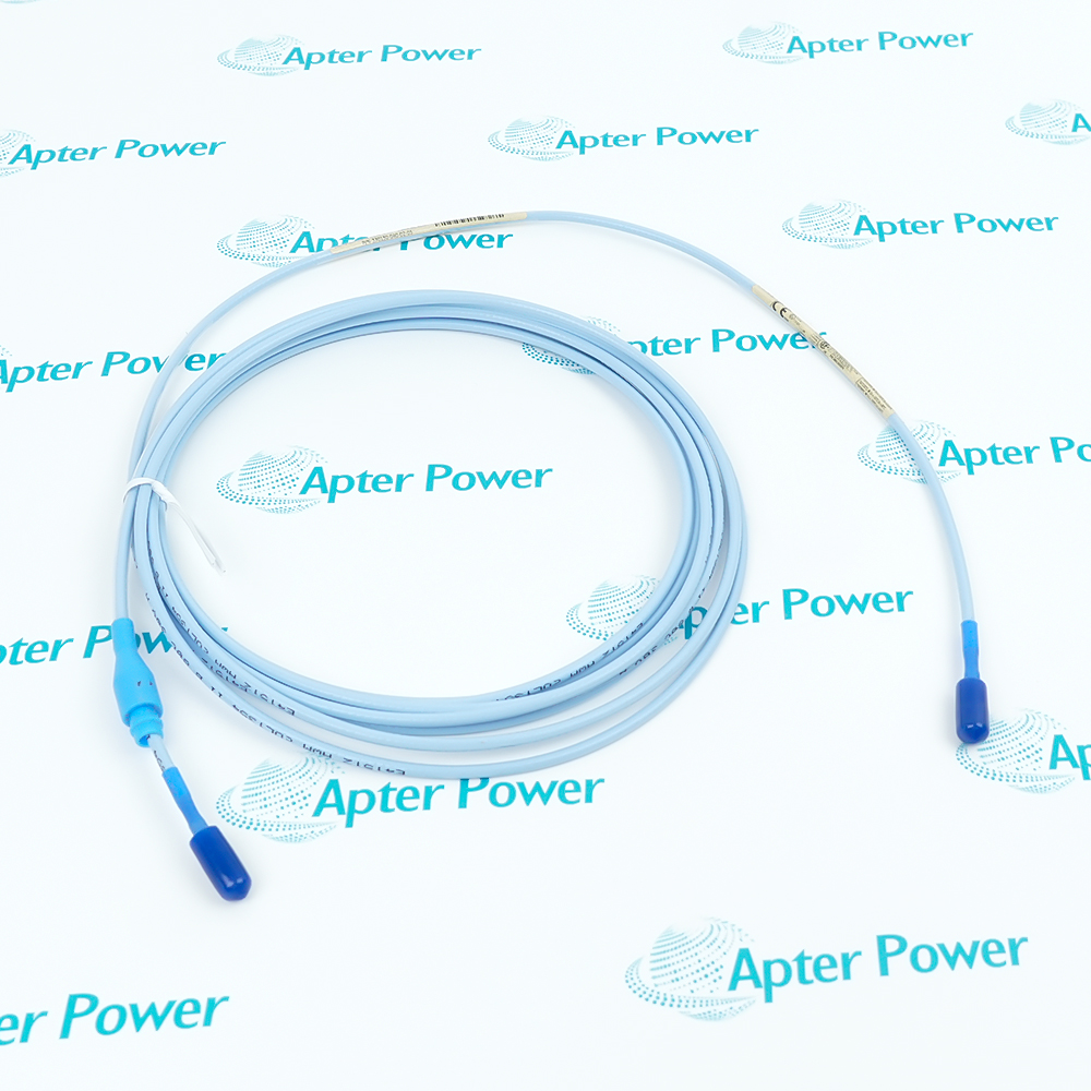
- The full 330103-06-15-10-12-05 order identity defines M10 x 1, unarmored, 60 mm unthreaded reach, 150 mm case, a 1 m FluidLoc lead and multiple approvals for its matched 3300 XL 8 mm measurement chain.
Flexible lead routing: The unarmored FEP-insulated lead supports a compact route and must be protected from abrasion, pulling and unsupported loading.
Fluid-migration control: The FluidLoc lead is selected to reduce fluid migration through the cable core in suitable oil-exposed installations.
The unarmored FEP-insulated lead supports a compact route and must be protected from abrasion, pulling and unsupported loading. The FluidLoc lead is selected to reduce fluid migration through the cable core in suitable oil-exposed installations. The order code does not include a factory-installed connector protector, so joint protection must follow the approved installation plan.
Published range, scale and frequency data apply to the complete matched 3300 XL 8 mm probe, extension cable and Proximitor Sensor under the stated target and calibration conditions. Commissioning therefore includes live gap, runout and receiving-channel response checks.
330103-06-15-10-12-05 Official Datasheet Excerpt
Bently Nevada 3300 XL 8 mm Proximity Transducer System Datasheet 141194 Rev. AN. Selected original pages covering the applicable product identity, technical data and system relationship.330103-06-15-10-12-05 Installation & Verification Guide
Model-specific field guide for identity capture, installed-fit checks, controlled replacement, commissioning and handover.
Application scope: Use 330103-06-15-10-12-05 for non-contacting shaft vibration, axial position or phase-reference measurement where its documented thread, reach, case and matched-system geometry fit the approved machine drawing.
Radial shaft vibration
Use 330103-06-15-10-12-05 where the M10 x 1 body and 150 mm case reproduce the documented bearing-housing geometry.Axial position measurement
Confirm target flatness, available travel and the 60 mm reach before setting the operating gap.Protected internal routing
Shield the unarmored lead from abrasion, sharp edges and unsupported weight.Oil-exposed probe ports
Use the FluidLoc execution where the approved installation requires resistance to fluid migration.
Photograph 330103-06-15-10-12-05 and confirm every option block before removal.
Record 60 mm reach, 150 mm case, insertion position and locknut location.
Do not pull on the lead or exceed the documented 25.4 mm bend radius.
Keep mating faces clean and add only the approved environmental protection required by the installation.
Combine the 1 m probe lead only with the extension cable and Proximitor Sensor selected for the intended system length.
Set live gap and compare static bias, runout and measurement response with the accepted baseline.
Alternative Names
Technical notes
Exact configuration: M10 x 1, unarmored, 60 mm unthreaded reach, 150 mm case; 1 m lead; ClickLoc connector, FluidLoc cable; multiple approvals
System boundary: Range, scale and frequency values belong to the complete matched 3300 XL 8 mm transducer chain, not the probe alone
Technical reference: Bently Nevada 3300 XL 8 mm Proximity Transducer System Datasheet 141194 Rev. AN

FAQ View All FAQ
-
How should the 60 mm reach of 330103-06-15-10-12-05 be reproduced?Record the installed datum and locknut position before removal, then confirm the 150 mm case places the tip at the same approved target gap.
-
What does the M10 x 1 execution of 330103-06-15-10-12-05 require at the machine port?Inspect thread form, engagement, sleeve clearance and target alignment; matching nominal diameter alone is not sufficient.
-
How does the unarmored lead affect routing of 330103-06-15-10-12-05?Protect the FEP lead from abrasion and tensile load while maintaining at least the documented bend radius.
-
What connection protection is selected on 330103-06-15-10-12-05?Option 12 does not include a factory-installed protector; use the approved site protection only where required.
-
How is total electrical length controlled for 330103-06-15-10-12-05?The probe contributes 1 m; add only the documented extension cable that matches the intended Proximitor Sensor system length.
-
Which target assumptions apply to 330103-06-15-10-12-05?Published performance uses the stated AISI 4140 reference target; verify target size, material, flatness and nearby conductive geometry for the actual machine.
-
How should 330103-06-15-10-12-05 be checked after installation?Set the approved live gap, confirm stable bias, then compare slow-roll runout and the intended vibration, position or phase response with the accepted record.
-
What does approval option 05 mean for 330103-06-15-10-12-05?The order code selects the documented multiple-approval execution; the installed circuit must still follow the applicable certified drawing.
Supporting new and legacy automation
-
Please try to be as accurate as possible with your search.
-
We can quote you on 1000s of specialist parts, even if they are not listed on our website.
-
We can't find any results for “”.
Related cases and sourcing guidance
View all case studiesYou May Also Like
Product Browsing History
-
330103-06-15-10-12-05Product Details -
330103-00-06-05-02-05Product Details -
330103-00-07-10-02-05Product Details -
330104-06-06-90-02-05Product Details -
330103-00-05-10-01-05Product Details -
330102-00-25-10-02-05Product Details -
330102-00-27-10-02-05Product Details -
330102-00-52-10-02-00Product Details -
84661-12Product Details -
2711P-T15C21D8SProduct Details
-
Whatsapp: +86 18030235313
Send us a message. -
sales13@apterpower.com
Complete our online form. -
+86 18030235313
Speak to our team in your native language.