Speak to a sourcing specialist
sales13@apterpower.com

X20DC2395

Counter Module
Ships by Thursday, November 12
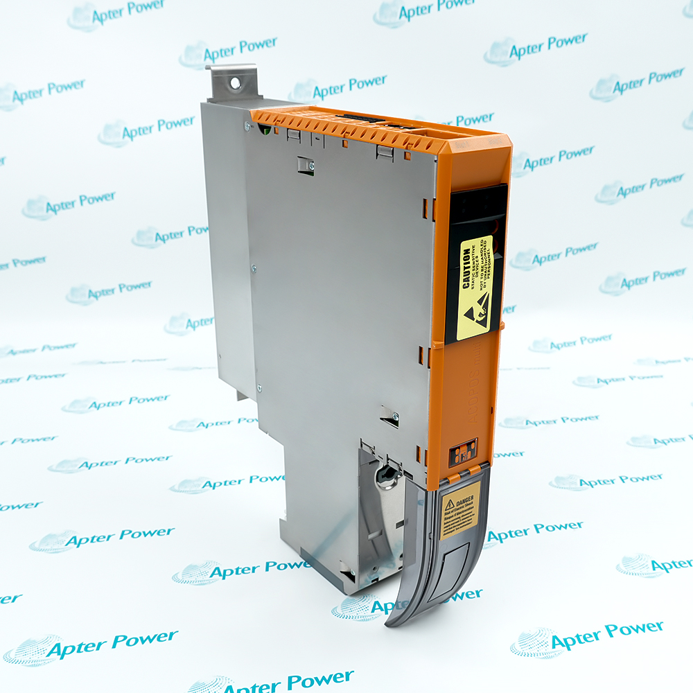
Product image is representative; revision or series may vary. Contact us to request a specific version.

Product Describe:

B&R X20DC2395 is a configurable four-channel counter module supporting encoder acquisition, event counting, time measurement and two PWM outputs.
  • Manufacturer part number
    X20DC2395
  • Shipping
    Swift global dispatch
  • Condition
    New, original product
  • Shipping size (est.)
    9.8cm x 5.7cm x 1.2cm
  • Country of Origin
    Austria
Get a quick price for X20DC2395
E-mail *
Mobile *
Company
Content *
Quantity *
Upload (gif, jpg, jpeg, png, bmp, doc, docx, xls, xlsx, ppt, pdf, csv)
For more information on how your data is processed and stored by Apterpower please read our privacy policy

What happens after you enquire

  • 0

    Review your reference

    Send the complete B&R X20DC2395 reference, label photographs and quantity. Include the existing digital channels arrangement.

  • 1

    Confirm the offer

    Review the offered revision, condition, included items and documents against the installation requirements.

  • 2

    Arrange dispatch

    Confirm quantity, dispatch date, lead-time start and delivery details in the quotation.

  • Match the complete marking

    Match the complete B&R X20DC2395 marking, hardware revision and selected configuration to the installed position. Check digital channels and incremental input against the installed configuration.

  • Check the offered item before ordering

    Request label and connection photographs. Have your maintenance team compare the offered X20DC2395 with the installed equipment and applicable B&R instructions.

Technical specifications for X20DC2395

  • Manufacturer:
    B&R
  • Product Category:
    PLC Systems
  • Spare Part Number:
    X20DC2395
  • Weight:
    0.02 kg
  • Tariff Code:
    8537101190
  • Digital channels:
    4 inputs, 2 also configurable as outputs
  • Incremental input:
    24 V asymmetrical; up to 100 kHz
  • SSI interface:
    1 encoder; up to 125 kbit/s
  • SSI coding:
    Gray or binary
  • Counter size:
    16/32-bit
  • Encoder supply:
    Module-internal; 600 mA maximum
  • Output current:
    0.1 A per channel; 0.2 A total
  • Output modes:
    Push, pull or push-pull
  • PWM period:
    41.6 microseconds to 1.36 s
  • PWM duty resolution:
    0.1%
  • Input voltage:
    24 V DC -15%/+20%
  • Internal I/O power:
    1.4 W

Information

Overview Downloads Applications / Compatibility Product Precautions
  • B&R X20DC2395 shares its terminal resources between several motion and pulse functions, allowing one station position to handle a selected mixture of input and output tasks.
Digital channels: 4 inputs, 2 also configurable as outputs
Incremental input: 24 V asymmetrical; up to 100 kHz
SSI interface: 1 encoder; up to 125 kbit/s
The four channels can serve one SSI absolute encoder, one ABR incremental encoder, two AB encoders or four event counters. Two channels can additionally operate as outputs; the maximum counts describe alternative allocations, not independent simultaneous capacities.

Incremental inputs accept 24 V asymmetrical signals at up to 100 kHz. SSI uses Gray or binary coding at up to 125 kbit/s. The module-internal encoder supply provides up to 600 mA and is protected against short circuit and overload.

The two outputs support push, pull or push-pull operation at 0.1 A each. Input edge events can control outputs directly; preserve the channel allocation, pulse period and electrical load before restoring an event-driven machine function.
Controller platform reference: B&R Counter Module. Use the applicable installation instructions.
Original B&R technical material applicable to X20DC2395, covering function, interfaces and operating limits. Installation topics include: channel count checks, ssi coding checks, output current checks.
Original manufacturer pages retain their technical context. Use the Apter Power guide with the applicable manufacturer instructions and approved installation design.
System and supply context: The counter module is applied in the Encoder or pulse / Shared input channels / Counter/time engine / X20 data or PWM arrangement. Select associated equipment for the actual channel or installation.

Application scope: Maximum encoder, counter and PWM counts are alternative allocations of shared terminals. The examples below address the stated product function.
Prepare B&R X20DC2395 for its configured installation using these checks.
Allocate the four shared channels

Draw the installed channel map before changing the module.

Check the encoder electrical level

Confirm 24 V asymmetrical encoder signals rather than assuming a differential line-driver interface.

Set SSI word interpretation

Retain the selected Gray or binary coding, word length and clock settings.

Preserve incremental direction

Mark A, B and reference signals before disconnecting.

Limit the output load

Check each output against its 0.1 A nominal rating and the 0.2 A total.

Inspect PWM timing

Verify the configured period and duty with a suitable instrument at the output.

Alternative Names

B&R X20DC2395

Technical notes

Check the encoder electrical level: Confirm 24 V asymmetrical encoder signals rather than assuming a differential line-driver interface. Record the encoder supply loading and leave the machine unable to move while the pulse wiring is disturbed.

Limit the output load: Check each output against its 0.1 A nominal rating and the 0.2 A total. Restore the push, pull or push-pull selection only after confirming the connected load and reference wiring.

Release the assigned functions: Record the accepted encoder positions, pulse counts, output waveform and timing scale for the functions actually used. Keep unused shared channels in their intended configuration before re-enabling motion.


FAQ View All FAQ

  • Can X20DC2395 run four event counters and two independent PWM channels at once?
    The functions share four physical channels, and two channels can be outputs. A mixed arrangement must respect the terminal allocation; the maximum function counts are not additive.
  • Which absolute encoder formats can X20DC2395 read?
    The SSI interface accepts Gray or binary coding with a 32-bit counter size and a maximum transfer rate of 125 kbit/s.
  • What is the incremental encoder frequency limit of X20DC2395?
    The 24 V asymmetrical incremental inputs support up to 100 kHz with fourfold evaluation.
  • How much current can the two X20DC2395 outputs supply?
    Each output is rated 0.1 A, with 0.2 A total nominal output current. The actual load and switching conditions must also meet the output limits.
  • What PWM timing range does X20DC2395 support?
    The period can be set from 41.6 microseconds to 1.36 seconds, with pulse duration from 0 to 100% and 0.1% duty resolution.
  • Can an input event operate a X20DC2395 output without a normal application write?
    Yes. Output setting and clearing can be controlled by events as well as by the application, provided that the selected channel functions are configured consistently.
  • Which timing quantities can X20DC2395 measure?
    Its timing functions include gate time, period duration and edge offsets between channels, with continuous or triggered measurement.
  • Why must all X20DC2395 signal cables be shielded?
    Shielded signal wiring is required for the counter and encoder interfaces. Preserve the shield arrangement to avoid false edges or corrupted encoder acquisition.
SPEAK TO OUR TEAM
Let’s find the right solution for you.
Send us the part number, quantity and delivery destination. Our team will help confirm availability and lead time.
  • Whatsapp: +86 18030235313

    Send us a message.
  • sales13@apterpower.com

    Complete our online form.
  • +86 18030235313

    Speak to our team in your native language.